You Can JTAG Debug An ESP32 With An FTDI Chip By Wiring TDI, TDO, TCK, TMS, GND, And Vtarget Correctly, Then Running OpenOCD With ESP-IDF Or PlatformIO.
Direct Answer
An FTDI chip works as a USB-To-JTAG bridge between your computer and the ESP32. The most common choices are FT2232H, FT2232HL, FT232H, ESP-Prog, and ESP-WROVER-KIT. ESP32 JTAG debugging usually needs OpenOCD, GDB, correct USB drivers, stable 3.3 V logic, and clean wiring.
What FTDI Chip Should You Use For ESP32 JTAG Debugging?
Use FT2232H Or FT2232HL If You Want The Most Reliable FTDI-Based ESP32 Debug Probe.
FT2232H and FT2232HL provide two USB channels. One channel can handle JTAG, while the other can support UART. That is why ESP-Prog and ESP-WROVER-KIT use FT2232-based designs. FT232H can also work, but it has one channel, so it is less convenient for combined debug and serial monitoring.
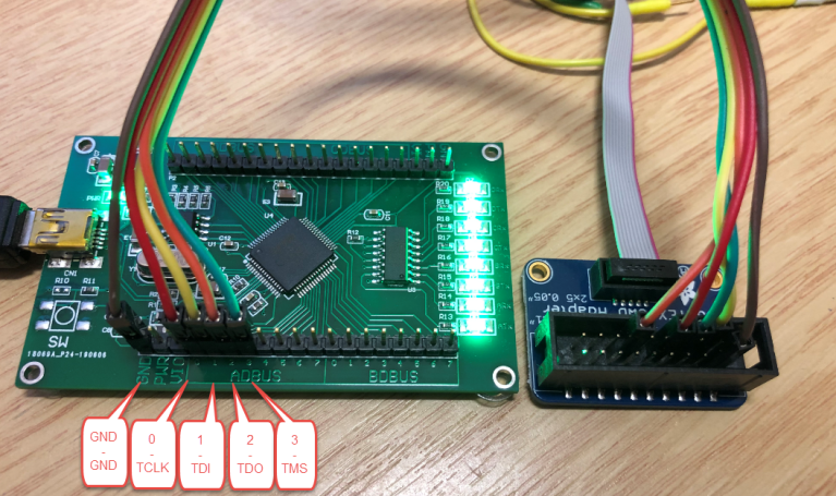
ESP32 JTAG Pinout For FTDI Connection
Use These ESP32 Classic JTAG Pins:
| ESP32 Pin | JTAG Signal | FTDI Direction |
|---|---|---|
| GPIO12 | TDI | FTDI To ESP32 |
| GPIO15 | TDO | ESP32 To FTDI |
| GPIO13 | TCK | FTDI Clock |
| GPIO14 | TMS | FTDI Mode Select |
| GND | GND | Common Ground |
| 3.3 V / Vtarget | Vref | Logic Reference |
The minimum JTAG connection needs TDI, TDO, TCK, TMS, And GND. Some adapters also need Vtarget to detect the ESP32 logic voltage.
Important GPIO12 Warning
GPIO12 Is Not Just A JTAG Pin On ESP32.
GPIO12 is also a bootstrapping pin. If the FTDI adapter drives it incorrectly during reset, the ESP32 may boot with the wrong flash voltage setting. This can cause boot failure, unstable flashing, or a board that looks dead during debugging. Keep the wiring short and avoid external pull circuits on JTAG pins.
Hardware Checklist Before Debugging
Power The ESP32 Board Separately.
Do not expect the FTDI JTAG adapter to power the full ESP32 board. Connect common GND directly between the FTDI adapter and ESP32. Keep JTAG wires short. Avoid breadboards when possible. Make sure GPIO12, GPIO13, GPIO14, and GPIO15 are not used by LEDs, buttons, SPI devices, or other circuits.
Windows Driver Setup
Use WinUSB For The FTDI JTAG Interface.
On Windows, OpenOCD usually needs WinUSB on the FTDI JTAG interface. For ESP-Prog and many FT2232HL boards, Interface 0 is the JTAG side. Do not replace the driver for the UART interface unless your specific adapter requires it. Zadig is commonly used to set the JTAG interface to WinUSB.
macOS Driver Setup
Remove Conflicting FTDI Drivers If OpenOCD Cannot Open The Device.
Some macOS setups load FTDI serial drivers before OpenOCD can access the JTAG interface. If the debugger cannot open the FTDI device, check whether an old FTDIUSBSerialDriver is holding the adapter. Avoid using the lower-numbered ESP-Prog serial port as a monitor port during debugging.
Linux Driver Setup
Install Udev Rules Before Debugging.
On Linux, FTDI debug problems often come from USB permission issues. Add the correct udev rule, reconnect the adapter, and confirm that your user belongs to the plugdev group. If OpenOCD says “unable to open ftdi device,” check permissions before changing the wiring.
OpenOCD Command For ESP32 With FTDI
Use This Basic OpenOCD Pattern:
openocd -f interface/ftdi/esp32_devkitj_v1.cfg -f target/esp32.cfgFor ESP-WROVER-KIT, Espressif often shows a board-level configuration such as:
openocd -f board/esp32-wrover-kit-3.3v.cfgIf OpenOCD cannot find the config file, check the OpenOCD scripts path and your ESP-IDF environment.
PlatformIO Configuration
Use ESP-Prog Settings For FTDI-Based Debugging.
[env:esp32dev]
platform = espressif32
board = esp32dev
framework = arduino
debug_tool = esp-prog
debug_init_break = tbreak setup
If you want to upload firmware through JTAG, add:
upload_protocol = esp-progDo not set debug_port to a serial COM port unless your debug method specifically requires it. JTAG does not debug through the normal UART monitor port.
Can You Upload ESP32 Firmware Through JTAG?
Yes, ESP32 Firmware Can Be Written Through JTAG With OpenOCD.
Espressif documents program_esp for writing an application image through OpenOCD. However, UART flashing is often simpler for first setup. JTAG flashing can fail if the running firmware has reconfigured GPIO12 to GPIO15 or if the JTAG wiring is unstable.
ESP32-S3, ESP32-C3, And Built-In USB JTAG
Do Not Treat Every ESP32 Family The Same.
Classic ESP32 usually needs an external JTAG adapter, such as ESP-Prog or an FTDI-based board. ESP32-S3 and ESP32-C3 can support USB JTAG on suitable boards, so an FTDI chip may not be necessary. Check the exact chip, board wiring, and USB connector design before buying a debugger.
Why OpenOCD Finds The FTDI Chip But Debugging Still Fails
A Detected FTDI Chip Does Not Prove The ESP32 JTAG Chain Is Working.
If OpenOCD can open the adapter but reports “all ones,” “all zeroes,” or scan-chain errors, the problem is usually between the adapter and ESP32. Check TDI/TDO direction, short wires, common ground, target power, and whether another circuit is connected to the JTAG pins.
Best Adapter Speed For Stable ESP32 JTAG Debugging
Start Slow, Then Increase Speed.
Many users chase high JTAG clock speed too early. Start around 500 kHz to 1 MHz when testing a new FTDI adapter or loose jumper wiring. After the connection becomes stable, increase speed gradually. If high-speed debugging fails, check signal quality before blaming OpenOCD.
Common Error Fixes
| Error Or Symptom | Likely Cause | Fast Fix |
|---|---|---|
| Unable To Open FTDI Device | Wrong Driver Or Permission | Use WinUSB Or Udev Rules |
| JTAG Scan Chain Failed | Wiring Error | Check TDI, TDO, TCK, TMS |
| All Ones Or All Zeroes | Floating Or Reversed Signal | Shorten Wires And Check GND |
| Debug Starts Then Freezes | Clock Or Reset Issue | Lower Adapter Speed |
| Board Stops Booting | GPIO12 Strap Conflict | Check Pullups And FTDI Idle State |
| Breakpoint Not Hit | Optimized Build | Use Debug Build Settings |
Should You Use FTDI Or ESP-Prog?
Use ESP-Prog If You Want The Fastest Setup.
ESP-Prog already uses an FT2232HL chip and provides ESP32-friendly program and JTAG interfaces. Use a generic FT2232H board if you want lower cost or a custom fixture. Use FT232H only when you understand its single-channel limitation and do not need a combined UART channel.
PCB Design Tips For ESP32 JTAG Debugging
Reserve A JTAG Header During PCB Design.
Expose GPIO12, GPIO13, GPIO14, GPIO15, GND, 3.3 V reference, EN, TXD0, RXD0, and GPIO0 if space allows. Place the header near the ESP32 module. Avoid long JTAG traces. Do not place heavy capacitive loads or external circuits on the JTAG pins.
When Not To Use JTAG Debugging
Do Not Use JTAG For Every Small Bug.
Serial logs are faster for simple boot messages, Wi-Fi status, and sensor readings. JTAG is more useful for hard faults, FreeRTOS task problems, memory corruption, startup bugs, and code that behaves differently when timing changes. For simple output checks, idf.py monitor or serial logging may be enough.
Final Debugging Workflow
Start With A Blink Project.
First, confirm UART flashing works. Second, connect FTDI JTAG wiring. Third, fix the USB driver. Fourth, run OpenOCD. Fifth, start GDB or VS Code debugging. Sixth, add breakpoints. Seventh, move to your real firmware only after the simple test project works.
FAQ
Can I Use Any FTDI Chip For ESP32 JTAG?
No. Use an FTDI chip supported by OpenOCD JTAG mode. FT2232H, FT2232HL, and FT232H are common choices. A normal FT232RL USB-UART chip is not enough for JTAG debugging.
Is ESP-Prog Just An FTDI Debugger?
ESP-Prog is an Espressif development and debugging board based on FT2232HL. It supports firmware download, serial communication, and JTAG debugging for ESP32 projects.
Do I Need UART If I Already Have JTAG?
You can debug through JTAG, but UART is still useful for boot logs, serial monitor output, and recovery flashing. For development boards, keep both available.
Why Does My ESP32 Debugger Need 3.3 V?
The FTDI adapter needs to match the ESP32 JTAG logic level. ESP32 JTAG pins use the 3.3 V domain, so the adapter must support that voltage range.
Can JTAG Debug FreeRTOS Tasks On ESP32?
Yes. ESP-IDF debugging supports OpenOCD and GDB workflows for ESP32, and Espressif’s tooling includes support for multi-core FreeRTOS debugging.