Introduction
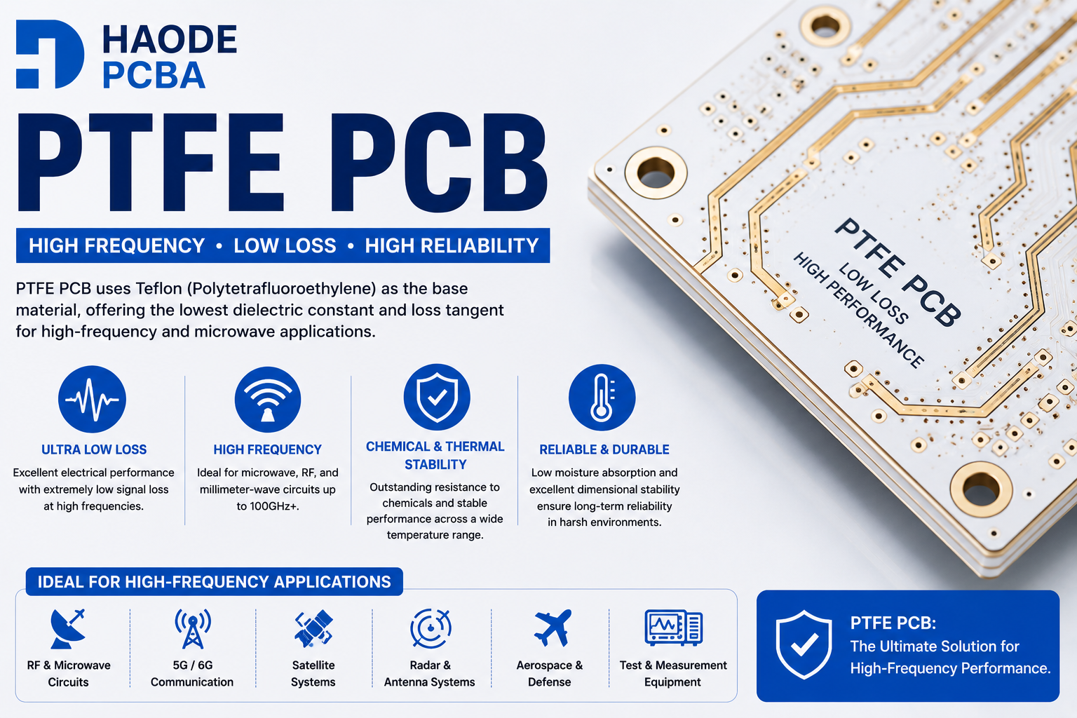
PTFE PCB is one of the most advanced high-frequency circuit board solutions used in RF, microwave, aerospace, and communication systems. Also known as Teflon PCB, PTFE-based circuit boards provide extremely low dielectric loss, excellent electrical stability, and reliable performance at high frequencies.
Unlike conventional FR4 PCB materials, PTFE PCB materials are specifically designed for applications where signal integrity and transmission efficiency are critical. They are widely used in radar systems, satellite communication, microwave circuits, automotive sensors, and advanced wireless equipment.
Choosing the correct PTFE PCB material and manufacturing partner is essential because PTFE materials require specialized processing techniques compared with standard PCB laminates.
Quick Answer
A PTFE PCB is a high-frequency printed circuit board manufactured using polytetrafluoroethylene (PTFE) laminate materials. PTFE provides extremely low dielectric loss, stable dielectric properties, and excellent microwave performance, making it ideal for RF, microwave, radar, aerospace, and satellite applications.
What Is PTFE PCB?
PTFE PCB is a circuit board that uses PTFE-based dielectric material as the substrate instead of traditional epoxy-based FR4.
PTFE, commonly known as Teflon, is a fluoropolymer material with outstanding electrical properties.
The material provides:
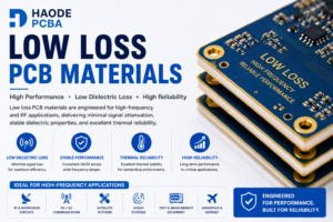
- Very low dielectric loss
- Stable dielectric constant
- Excellent chemical resistance
- Low moisture absorption
- Wide operating temperature range
Because of these characteristics, PTFE PCB materials are widely used in demanding high-frequency applications.
Why Is PTFE Used For High Frequency PCB?
As electronic systems move toward higher frequencies, signal loss becomes a major design challenge.
Standard PCB materials may cause:
- Higher insertion loss
- Signal attenuation
- Impedance variation
- Reduced transmission efficiency
PTFE solves these problems by providing:
Extremely Low Dielectric Loss
PTFE materials allow high-frequency signals to travel with minimal energy loss.
This improves:
- Signal strength
- Transmission distance
- RF efficiency
Stable Electrical Performance
PTFE maintains consistent electrical properties across a wide frequency range.
This helps engineers achieve:
- Accurate simulation
- Reliable impedance control
- Stable RF performance
Excellent High Temperature Performance
PTFE PCB materials can operate in demanding environments.
Benefits include:
- Thermal stability
- Long-term reliability
- Resistance to environmental changes
PTFE PCB Vs FR4 PCB
| Feature | PTFE PCB | FR4 PCB |
|---|---|---|
| Frequency Performance | Excellent | Moderate |
| Dielectric Loss | Extremely Low | Higher |
| RF Performance | Excellent | Limited |
| Temperature Stability | Excellent | Good |
| Manufacturing Difficulty | Higher | Easier |
| Cost | Higher | Lower |
FR4 remains the preferred choice for general electronic products, while PTFE PCB is selected for advanced RF and microwave applications.
PTFE PCBA Material Types
Different PTFE laminates are designed for different performance requirements.
Rogers PTFE Materials
Rogers provides some of the most widely used PTFE-based PCBA materials.
Popular options include:
RT/duroid 5880
Designed for:
- Microwave circuits
- Satellite communication
- Aerospace systems
Advantages:
- Ultra-low loss
- Excellent frequency stability
RT/duroid 6002
Suitable for:
- Microwave components
- High-frequency communication
Advantages:
- Stable dielectric performance
- Low transmission loss
RO3003
Designed for:
- Millimeter-wave applications
- Automotive radar
- Antenna systems
Advantages:
- Stable Dk
- Excellent thermal reliability
PTFE PCB Applications
Radar Systems
PTFE PCBA is widely used in radar systems because radar requires extremely accurate high-frequency signal transmission.
Applications include:
- Automotive radar
- Military radar
- Weather radar
- Tracking systems
Satellite Communication
Satellite systems require materials that maintain performance under extreme conditions.
PTFE PCBA supports:
- Low signal loss
- Reliable communication
- Long operational life
Applications include:
- Satellite antennas
- Space communication equipment
- Navigation systems
Microwave Electronics
Microwave circuits require excellent electrical performance.
Applications include:
- Microwave filters
- RF amplifiers
- Oscillators
- Transceivers
5G Communication
Modern wireless networks require advanced PCB materials.
PTFE PCBA supports:
- High-frequency transmission
- Antenna performance
- Low signal attenuation
Applications include:
- 5G antennas
- RF modules
- Communication equipment
PTFE PCBS Design Considerations
Designing PTFE PCBs requires different considerations compared with FR4.
Controlled Impedance Design
RF circuits require precise impedance control.
Important parameters include:
- Trace width
- Dielectric thickness
- Copper thickness
- Material Dk
Common impedance requirements:
- 50Ω RF circuits
- Differential transmission lines
Stackup Design
A proper stackup improves:
- Signal integrity
- EMI performance
- Manufacturing reliability
Engineers should consider:
- Ground plane placement
- Dielectric thickness
- Layer arrangement
Copper Surface Treatment
At high frequencies, copper roughness affects signal loss.
PTFE PCBA designs often require:
- Low-profile copper
- Smooth copper foil
- Controlled surface treatment
PTFE PCB Manufacturing Challenges
Manufacturing PTFE PCBA is more difficult than standard FR4 PCBA production.
Material Handling
PTFE materials require careful control because they have different mechanical characteristics.
Important factors include:
- Storage conditions
- Surface preparation
- Processing parameters
Drilling Challenges
PTFE materials are softer than FR4.
Manufacturers must carefully control:
- Drill parameters
- Hole quality
- Debris removal
Lamination Process
PTFE requires specialized lamination techniques.
Incorrect processing may affect:
- Layer bonding
- Dielectric thickness
- Electrical performance
Surface Finish Selection
Common finishes include:
- ENIG
- Immersion Silver
- OSP
The selection depends on:
- Frequency requirements
- Assembly process
- Reliability expectations
PTFE PCB Cost Factors
PTFE PCBA cost is influenced by:
Material Cost
PTFE laminates are significantly more expensive than standard FR4.
Manufacturing Complexity
Special processing increases production costs.
Layer Count
More layers increase:
- Material usage
- Processing time
- Inspection requirements
Testing Requirements
RF testing and impedance verification may increase overall cost.
How To Reduce PTFE PCB Cost
Select The Correct Material
Not every high-frequency application requires the highest-performance PTFE laminate.
Optimize PCB Design
Good layout reduces:
- Manufacturing complexity
- Material waste
- Production risks
Work With An Experienced Manufacturer
An experienced PTFE PCB manufacturer can provide:
- Material recommendations
- DFM support
- Process optimization
- Reliable production
Why Choose Haode PCBA For PTFE PCB Manufacturing?
Our capabilities include:
- PTFE material sourcing
- Rogers PCB fabrication
- High Frequency PCB manufacturing
- RF PCB production
- Controlled impedance testing
- SMT assembly
- Prototype and volume production
With engineering experience and advanced manufacturing capability, Haode PCBA supports customers developing reliable high-frequency electronic products.
Conclusion
PTFE PCBA is one of the most important high-performance PCBA solutions for microwave, RF, aerospace, and communication applications.
Its extremely low dielectric loss, excellent electrical stability, and high-frequency reliability make it an ideal choice when conventional FR4 materials cannot meet performance requirements.
For demanding RF and microwave projects, choosing an experienced PTFE PCB Manufacturer ensures better material selection, manufacturing quality, and long-term product reliability.
s