Knowing How To Test A Circuit Board Is Essential For Diagnosing Faults, Verifying Assembly Quality, And Ensuring Reliable Performance In Electronic Devices. Whether You Are Working With A Simple DIY Project, A Prototype PCB, Or A Complex Electronic Assembly, Proper Testing Helps Identify Issues Such As Short Circuits, Open Circuits, Faulty Components, And Poor Solder Joints. This Guide Explains Practical Methods, Tools, And Best Practices To Help You Test A Circuit Board Safely And Effectively.
Why Circuit Board Testing Matters
Testing A Circuit Board Confirms That The Design, Assembly, And Components Work As Intended. Without Proper Testing, Hidden Problems May Lead To Device Failure, Unstable Performance, Or Safety Risks. Many Engineers And Technicians Perform PCB Testing During Prototyping, After Assembly, And Before Final Product Integration.
Common Reasons To Learn How To Test A Circuit Board Include Troubleshooting Non-Working Electronics, Validating New PCB Designs, Checking Repaired Boards, And Performing Quality Control In Manufacturing.
Tools Needed To Test A Circuit Board
To Start Testing, You Will Need Basic Electronic Test Equipment. A Digital Multimeter Is The Most Common Tool Used For Measuring Voltage, Resistance, And Continuity. An Oscilloscope Is Useful For Observing Signals And Waveforms In More Advanced Circuits. A Power Supply Provides Controlled Voltage During Testing.
Other Helpful Tools Include A Logic Analyzer For Digital Circuits, A Function Generator For Signal Input, And Magnification Tools For Visual Inspection. For Manufacturing Environments, Automated Test Equipment And PCB Test Fixtures May Also Be Used.
Step 1: Perform A Visual Inspection
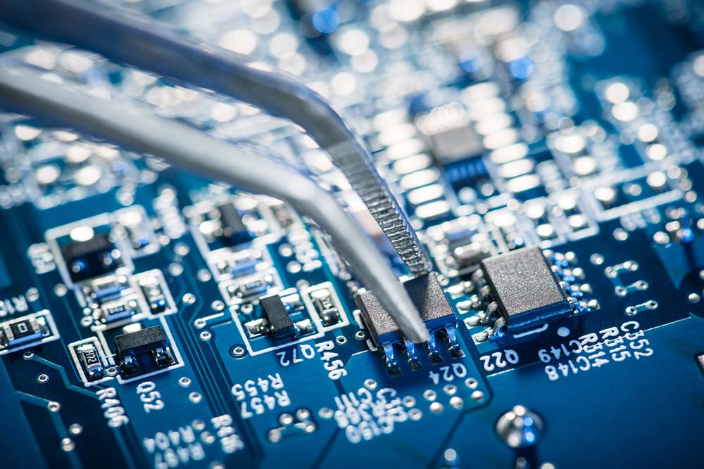
Before Applying Power, Always Begin With A Careful Visual Check. Look For Burn Marks, Cracked Components, Missing Parts, Misaligned ICs, And Cold Solder Joints. Check For Solder Bridges Between Pads And Ensure All Components Are Placed Correctly According To The PCB Layout.
Visual Inspection Is A Simple But Important Step In How To Test A Circuit Board Because Many Issues Can Be Found Without Using Any Instruments.
Step 2: Check For Short Circuits
Using A Multimeter In Continuity Mode, Test Between Power And Ground To Ensure There Is No Short Circuit. If The Multimeter Beeps Or Shows Very Low Resistance, There May Be A Short On The Board.
You Can Also Check Individual Traces And Components To Confirm Proper Connections. Detecting Shorts Early Helps Prevent Damage When Power Is Applied.
Step 3: Verify Power Supply Lines
Next, Apply Power Carefully And Measure Voltage At Key Points On The Board. Confirm That The Input Voltage Matches The Design Requirements. Then Check Voltage Regulators, IC Power Pins, And Other Critical Nodes.
Stable And Correct Voltage Levels Are Essential For Proper Circuit Operation. If The Voltage Is Too High, Too Low, Or Unstable, The Circuit May Not Function Correctly.
Step 4: Test Individual Components
Testing Components Is A Key Part Of How To Test A Circuit Board. You Can Use A Multimeter To Check Resistors, Capacitors, Diodes, And Transistors. For Integrated Circuits, You May Need To Refer To Datasheets And Measure Input And Output Signals.
If A Component Appears Faulty, Replace It And Test The Circuit Again. In Some Cases, Removing The Component From The Board Provides More Accurate Results.
Step 5: Check Signal Flow
For More Advanced Testing, Use An Oscilloscope To Observe Signal Behavior Across The Circuit. This Helps Verify That Signals Travel Correctly From Input To Output.
Check Clock Signals, Data Lines, And Analog Waveforms If Applicable. If The Signal Stops Or Distorts At A Certain Point, That Area May Contain The Fault.
Step 6: Perform Functional Testing
After Basic Electrical Checks, Perform A Functional Test To Confirm That The Circuit Works As Intended. This Step In How To Test A Circuit Board Involves Running The Board In Its Real Application Or Simulated Environment.
For Example, A Power Supply Board Should Deliver Stable Output Voltage, While A Control Board Should Respond To Inputs Correctly. Functional Testing Ensures The Entire System Operates Properly.
Common Circuit Board Testing Methods
There Are Several Standard PCB Testing Methods Used In Different Scenarios. Continuity Testing Checks For Proper Electrical Paths. In-Circuit Testing Measures Individual Components On The Board. Functional Testing Verifies Overall Performance.
In Manufacturing, Automated Optical Inspection Is Used To Detect Solder Defects And Placement Issues. X-Ray Inspection Helps Check Hidden Solder Joints In Complex Packages Like BGA. Flying Probe Testing And Bed Of Nails Testing Are Also Used For High-Volume PCB Assembly.
Common Problems Found During Testing
When Learning How To Test A Circuit Board, It Helps To Know Typical Issues. These Include Short Circuits, Open Circuits, Cold Solder Joints, Incorrect Component Placement, Damaged ICs, And Power Supply Problems.
Other Issues May Include Signal Noise, Poor Grounding, Or Thermal Problems. Identifying These Problems Early Improves Reliability And Reduces Repair Costs.
Safety Tips For Circuit Board Testing
Always Follow Basic Safety Practices When Testing A Circuit Board. Ensure The Power Supply Matches The Design Requirements. Avoid Touching Live Circuits To Prevent Electric Shock. Use Proper Insulation And Grounding Techniques.
If You Are Working With High Voltage Or Sensitive Electronics, Take Extra Care To Protect Both Yourself And The Components. Electrostatic Discharge Protection Is Also Important When Handling Sensitive ICs.
Conclusion
Understanding How To Test A Circuit Board Is A Valuable Skill For Engineers, Technicians, And Hobbyists. By Combining Visual Inspection, Electrical Measurement, Signal Analysis, And Functional Testing, You Can Identify Problems Quickly And Ensure Reliable Performance. Whether You Are Troubleshooting A Faulty Device Or Validating A New Design, Proper PCB Testing Helps Improve Quality, Reduce Failures, And Build More Dependable Electronic Systems.