High Frequency PCB: Everything You Need To Know
If your electronic product operates above 500 MHz, choosing the right High Frequency PCB is just as important as selecting the right RF components. Standard FR-4 materials may introduce excessive signal loss, impedance variation, and electromagnetic interference, while specialized high-frequency laminates maintain signal integrity, improve transmission efficiency, and increase long-term reliability.
Whether you are designing a 5G communication module, automotive radar, satellite transceiver, GPS antenna, microwave amplifier, or high-speed digital interface, understanding High Frequency PCB technology helps reduce development risks and manufacturing costs while improving overall system performance.
Quick Answer
A High Frequency PCB is a printed circuit board manufactured with low-loss dielectric materials specifically engineered for radio frequency (RF), microwave, millimeter-wave, and high-speed digital applications. Compared with conventional FR-4 boards, high-frequency PCBs provide lower dielectric loss, more stable dielectric constant (Dk), tighter impedance control, lower insertion loss, and superior signal integrity across a wide frequency range.
Key Takeaways
- Designed for RF and microwave applications
- Stable dielectric constant (Dk)
- Low dielectric loss (Df)
- Excellent impedance consistency
- Lower insertion loss
- Better phase stability
- Reduced electromagnetic interference
- Superior thermal stability
- Ideal for 5G, radar, aerospace, and satellite systems
Table Of Contents
- What Is A High Frequency PCB?
- Why Standard FR-4 Is Not Enough
- How High Frequency PCBs Work
- Common High Frequency PCB Materials
- Dielectric Constant Explained
- Loss Tangent Explained
- High Frequency PCB Stackup Design
- Controlled Impedance
- Signal Integrity
- Manufacturing Process
- Quality Inspection
- Applications
- Cost Factors
- Material Comparison
- Design Tips
- FAQ
What Is A High Frequency PCB?
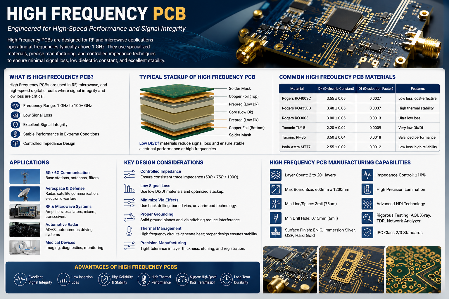
A High Frequency PCB is a specialized printed circuit board designed to transmit electrical signals with minimal attenuation at high frequencies. While traditional PCBs work well for low-speed digital circuits and general electronics, they become increasingly inefficient as signal frequencies rise into the hundreds of megahertz or gigahertz.
At these frequencies, electrical signals behave more like electromagnetic waves than simple currents. Small variations in dielectric properties, trace geometry, copper roughness, or manufacturing tolerances can significantly affect signal quality.
For this reason, high-frequency PCBs rely on advanced laminates with tightly controlled electrical properties and manufacturing processes capable of maintaining precise impedance and dimensional accuracy.
Why Standard FR-4 Is Not Suitable For High-Frequency Applications
FR-4 remains the world’s most widely used PCB substrate because it offers an excellent balance of cost, mechanical strength, and manufacturability. However, its electrical characteristics become less predictable as operating frequency increases.
The dielectric constant of FR-4 varies between manufacturers and even between production batches. In addition, its relatively high dielectric loss causes signals to weaken over long transmission paths. As operating frequency approaches several gigahertz, these limitations can reduce communication quality, increase bit error rates, and generate unwanted electromagnetic radiation.
Specialized high-frequency materials are engineered to overcome these challenges by providing:
- Stable dielectric constant over frequency
- Extremely low dielectric loss
- Lower moisture absorption
- Better thermal expansion control
- Improved dimensional stability
- Consistent impedance performance
These characteristics are essential for modern RF communication systems.
How Does A High Frequency PCB Work?
Unlike conventional digital circuits, RF signals require controlled transmission lines rather than simple conductive traces.
Each copper trace acts as a transmission line whose electrical characteristics depend on several variables:
- Trace width
- Copper thickness
- Dielectric thickness
- Dielectric constant
- Ground plane spacing
- Surface roughness
Engineers carefully calculate these parameters to achieve target impedances such as:
- 50 Ω Single-Ended
- 75 Ω Video Systems
- 90 Ω USB Differential Pair
- 100 Ω Ethernet Differential Pair
- 85 Ω PCIe Differential Pair
Accurate impedance matching minimizes signal reflections and maximizes power transfer between components.
Characteristics Of A High Frequency PCB
Compared with ordinary circuit boards, High Frequency PCB technology offers several important advantages.
Low Dielectric Loss
Signal attenuation decreases significantly, allowing longer transmission distances with minimal performance degradation.
Stable Dielectric Constant
Consistent dielectric properties simplify impedance calculations and reduce manufacturing variation.
Excellent Signal Integrity
Cleaner waveforms reduce timing errors, jitter, and communication failures.
Superior Thermal Stability
Advanced laminates maintain electrical performance under elevated temperatures.
Better Mechanical Stability
Reduced expansion and contraction improve long-term reliability during thermal cycling.
Lower Moisture Absorption
Low water absorption prevents changes in dielectric properties in humid environments.
Common High Frequency PCB Materials
Selecting the correct laminate is one of the most critical decisions in RF PCB design.
Rogers Materials
Rogers laminates are among the industry’s most widely recognized materials for microwave and RF applications.
Popular series include:
- RO4350B
- RO4003C
- RT/duroid 5880
- RO3003
- RO3010
These materials combine excellent electrical performance with reliable manufacturability.
Taconic Materials
Taconic laminates provide low-loss performance and are frequently used in aerospace, defense, and satellite communication systems.
Common products include:
- RF-35
- TLY Series
- TLC Series
- CER-10
Isola Materials
Isola develops high-performance laminates suitable for high-speed digital networking and advanced communication equipment.
Popular options include:
- Astra MT77
- I-Speed
- Tachyon
- TerraGreen
Panasonic Materials
Panasonic Megtron materials are widely adopted for AI servers, cloud computing infrastructure, and ultra-high-speed digital applications requiring exceptional signal integrity.
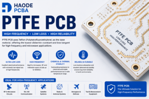
PTFE Materials
PTFE-based laminates provide some of the industry’s lowest dielectric loss values and are commonly selected for:
- Microwave antennas
- Millimeter-wave radar
- Satellite systems
- Aerospace electronics
Although PTFE materials offer outstanding electrical performance, they require specialized processing techniques due to their mechanical characteristics.
How To Select The Right High Frequency PCB Material
Choosing the right laminate depends on more than operating frequency alone. Engineers should evaluate several factors before making a decision.
Consider the following:
- Operating Frequency
- Signal Loss Budget
- Required Impedance Accuracy
- Thermal Performance
- Mechanical Strength
- Moisture Resistance
- Manufacturing Capability
- Assembly Process
- Reliability Requirements
- Total Project Cost
Balancing electrical performance with manufacturability helps achieve the best overall value for the project.