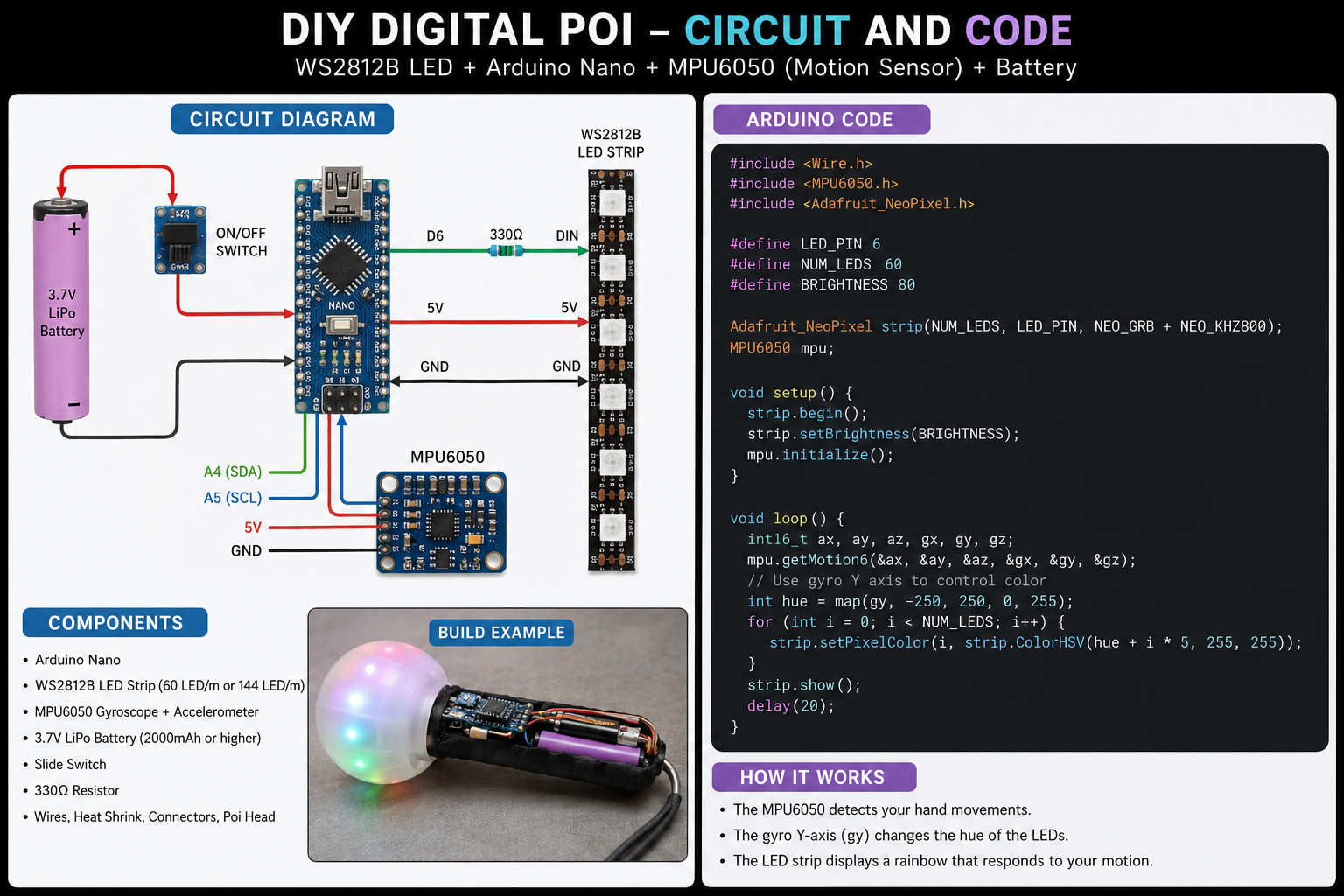
Diy Digital Poi Circuit And Code Introduction
Diy Digital Poi Circuit And Code Projects Combine Addressable LEDs, Embedded Programming, And Custom PCB Design To Create Dynamic Light Effects. A Typical Digital Poi System Includes A Microcontroller, LED Drivers, A Battery Circuit, And Firmware That Controls Patterns And Animations. Building A Custom Printed Circuit Board Makes The Device More Compact, Reliable, And Suitable For Prototyping Or Small-Volume Production.
Why Build A Digital Poi Circuit With A PCB?
Breadboards And Jumper Wires Work Well For Early Experiments, But A Custom PCB Improves Durability, Reduces Wiring Errors, And Simplifies Assembly. A Dedicated LED PCB Also Provides Better Power Distribution And Cleaner Signal Routing For Addressable RGB LEDs.
Main Components Of A Programmable LED Poi
- ESP32 Or Arduino Nano
- WS2812B Addressable LEDs
- Rechargeable Lithium Battery
- Charging And Protection Circuit
- Push Buttons And Connectors
- Custom PCB Assembly
- Embedded Animation Firmware
Designing A Digital Poi PCB
A Professional PCB Design Starts With A Circuit Schematic And Component Selection. Engineers Then Route Power And Data Traces, Add Protection Components, And Optimize The Board Layout To Prevent Voltage Drops And Signal Interference.
After The Design Is Finished, The Project Moves Into PCB Manufacturing And PCB Assembly, Turning A Prototype Into A Reliable And Production-Ready Device.