Inverter Power Circuit Board is one of the most important parts of modern power conversion systems. It controls and supports the electronic process that converts direct current into alternating current, allowing electrical devices and systems to operate efficiently in residential, commercial, industrial, and renewable energy applications.
From solar inverters and UPS systems to motor drives and power backup equipment, the Inverter Power Circuit Board plays a central role in managing power flow, switching control, thermal performance, and system reliability. In the electronics industry, this type of board may also be described as an inverter PCB, power inverter board, inverter control boards, inverter driver circuit board, or inverter motherboard, depending on the product structure and application.
What Is An Inverter Power Circuit Board
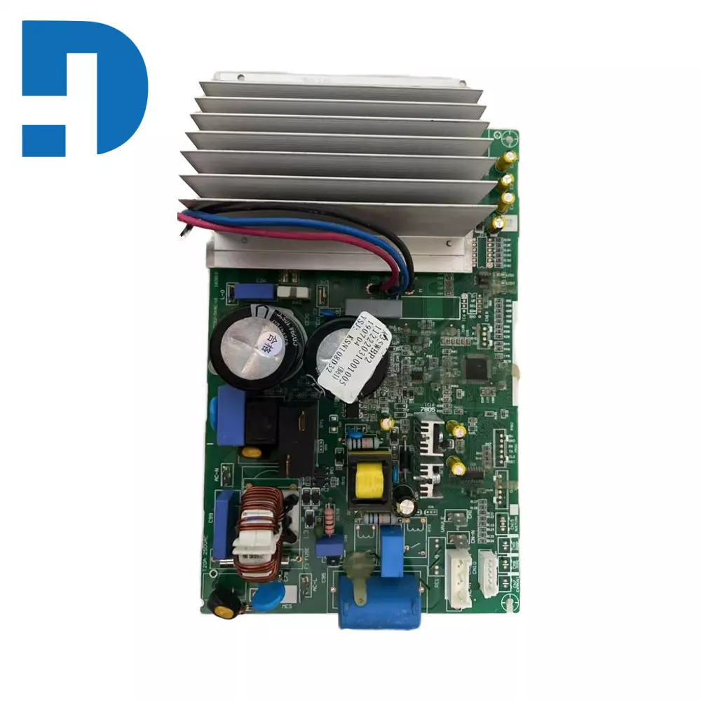
An Inverter Power Circuit Board is a printed circuit board designed for inverter systems that convert DC power into AC power. It provides the electrical pathways, component mounting platform, and control structure required for power switching, signal control, and output regulation.
A typical Power Inverter Circuit Boards may support:
- Power Conversion Control
- MOSFET Or IGBT Switching
- Voltage Regulation
- Frequency Generation
- Protection Functions
- Signal Feedback
- Thermal Monitoring
Because inverter systems often operate under high power and high switching conditions, the PCB design must support both electrical performance and heat management.
How An Inverter Power Circuit Board Works
An Inverter Power Circuit Boards works by coordinating the electronic components that convert incoming DC power into usable AC output. The board routes current through switching devices, control circuits, filters, and output sections.
In a basic inverter system, the process usually includes:
- DC Power Input
- Control Signal Generation
- High-Speed Switching
- Transformer Or Inductor Support
- Output Waveform Processing
- AC Power Delivery
The Inverter PCB Board allows these functions to operate in a structured and reliable way, helping the inverter provide stable voltage and frequency output.
Main Functions Of An Inverter Power Circuit Board
A high-quality Inverter Power Circuit Boards performs several critical functions inside the inverter system.
Power Conversion Support
The board connects the switching devices, capacitors, transformers, and control circuits needed for DC to AC conversion.
Signal Routing And Control
The PCB carries control signals between the microcontroller, driver circuits, feedback loops, and power stage.
Component Mounting
The board provides a stable platform for installing components such as MOSFETs, IGBTs, diodes, resistors, capacitors, and transformers.
Thermal Management
An Inverter Power PCB often needs to support heat dissipation through copper design, board material choice, and layout structure.
Protection And Monitoring
Many inverter boards also include circuits for overvoltage protection, overcurrent protection, short-circuit protection, and thermal shutdown functions.
Key Components On An Inverter Power Circuit Board
An Inverter Power Circuit Boards may contain many different electronic components depending on the power level and inverter design.
Common components include:
- MOSFETs
- IGBTs
- Gate Driver ICs
- Capacitors
- Resistors
- Diodes
- Transformers
- Inductors
- Microcontrollers
- Current Sensors
- Voltage Feedback Circuits
- Connectors
- Heat Dissipation Structures
Together, these parts allow the Power Inverter PCB to control switching, stabilize output, and protect the system during operation.
Types Of Inverter Power Circuit Boards
Different inverter applications require different Inverter Power Circuit Boards designs.
Solar Inverter Circuit Board
A Solar Inverter Circuit Boards is used in photovoltaic power systems to convert solar-generated DC power into AC electricity.
UPS Inverter PCB
A UPS Inverter PCB is used in uninterruptible power supply systems to provide backup AC power when the main source fails.
Motor Drive Inverter Board
A Motor Drive Inverter Boards controls frequency and voltage for motor speed regulation in industrial systems.
Home Power Inverter Board
A Home Inverter Circuit Boards is commonly used in household backup power systems and small inverter devices.
Industrial Inverter Control Board
An Industrial Inverter Control Boards is used in more demanding power systems where higher voltage, higher current, and stronger thermal performance are required.
Inverter Power Circuit Board Design Considerations
Designing an Inverter Power Circuit Boards requires careful attention to electrical performance, safety, and thermal control.
Important design factors include:
Copper Thickness
High-current inverter boards often require thicker copper to handle power flow safely.
Trace Width And Current Path
The board layout must support current capacity and reduce unnecessary resistance or heating.
Thermal Management
Power switching devices generate significant heat, so the PCB must support heat transfer and cooling.
Electrical Isolation
Proper spacing and isolation are important in inverter systems to improve safety and reduce interference.
EMI And Noise Control
Because inverter circuits switch at high speed, the PCB must help reduce electrical noise and electromagnetic interference.
Component Layout
A well-organized layout improves efficiency, assembly quality, and long-term reliability.
A strong Inverter PCB Design directly affects inverter performance and product lifespan.
Materials Used In Inverter Power Circuit Boards
The material selection of an Inverter Power Circuit Boards has a major influence on durability and thermal behavior.
Common materials include:
- FR-4 For Standard Inverter Boards
- High TG Material For Better Thermal Stability
- Heavy Copper PCB For High Current Applications
- Metal Core Support In Some Thermal Designs
- High Reliability Laminate For Industrial Use
For demanding applications, manufacturers may choose advanced PCB materials to improve insulation, heat resistance, and electrical stability.
Inverter Power Circuit Board Manufacturing Process
The manufacturing process of an Inverter Power Circuit Board is similar to other PCBs, but it often requires stronger process control because of the power-handling requirements.
The general process includes:
PCB Fabrication
The board layers are produced according to the inverter PCB design files.
Drilling And Plating
Holes are drilled and plated to create interconnections between layers when needed.
Solder Mask And Surface Finish
A solder mask protects the board, and the exposed pads receive a suitable finish such as HASL, ENIG, or other options.
PCB Assembly
Power devices, control ICs, capacitors, connectors, and other components are assembled onto the board.
Testing And Inspection
The finished Inverter Circuit Board is inspected and tested to confirm electrical quality and assembly accuracy.
Why Inverter Power Circuit Board Quality Matters
The quality of an Inverter Power Circuit Board directly affects the safety, efficiency, and stability of the final inverter product.
A poor-quality board may lead to:
- Overheating
- Unstable Output
- Switching Failure
- Shortened Product Life
- Electrical Noise Problems
- Component Damage
- Reduced Efficiency
A high-quality Power Inverter Board helps ensure strong electrical performance, better heat handling, and long-term reliability.
Applications Of Inverter Power Circuit Boards
An Inverter Power Circuit Boards is used in many power electronics products and systems.
Common applications include:
- Solar Inverters
- Home Backup Power Systems
- UPS Equipment
- Motor Drives
- Industrial Automation Systems
- Electric Vehicle Power Systems
- Battery Energy Storage Systems
- Renewable Energy Equipment
- Power Conversion Modules
- Smart Power Control Devices
Because inverter technology is widely used across modern electronics and energy systems, the demand for reliable inverter boards continues to grow.
Inverter Power Circuit Board Vs Standard PCB
Although an Inverter Power Circuit Boards is a type of PCB, it differs from a standard signal-level board in several ways.
| Feature | Inverter Power Circuit Board | Standard PCB |
|---|---|---|
| Main Function | Power Conversion And Control | General Signal Or Control Use |
| Current Handling | Higher | Usually Lower |
| Thermal Demand | High | Moderate |
| Layout Focus | Power Path And Switching | General Circuit Routing |
| Material Need | Often More Robust | Standard FR-4 Often Enough |
Because inverter systems deal with higher power, switching speed, and heat, they require a more specialized PCB design approach.
How To Choose The Right Inverter Power Circuit Board
When choosing an Inverter Power Circuit Boards, buyers and engineers should consider several important factors.
Power Rating
The board must match the voltage and current requirements of the inverter system.
Application Type
A solar inverter board may have different needs than a UPS board or motor drive board.
Thermal Performance
The PCB should support the heat load generated by the switching devices and power components.
Material Quality
Higher-performance laminate and copper design may be needed for demanding applications.
Assembly And Testing Standard
A reliable board should be manufactured and assembled with strong process control and inspection.
Long-Term Reliability
The PCB should support stable operation over time in the target environment.
Conclusion
An Inverter Power Circuit Board is a core platform in modern power electronics because it supports DC to AC conversion, power switching, signal control, and thermal management. Whether used as a solar inverter PCB, UPS inverter board, motor drive inverter circuit board, or home power inverter control board, it plays a major role in system performance and reliability.
For manufacturers, engineers, and OEM buyers, understanding the design, materials, functions, and applications of an Inverter Power Circuit Board is essential for building efficient and dependable inverter systems. A well-designed inverter PCB can improve power stability, support safe operation, and extend the service life of the final product.