
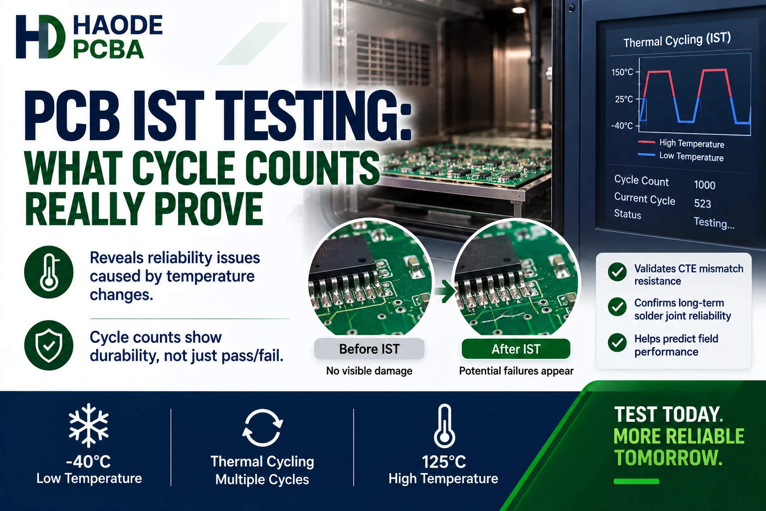
PCB IST testing heats and cools a representative coupon while continuously monitoring the resistance of its plated holes, vias, and internal-layer connections. The test helps identify latent interconnect defects and measures how many controlled thermal cycles the coupon survives before reaching a defined resistance-change threshold.
However, an IST result applies only to the tested coupon, structure, and protocol. Passing 500 cycles does not automatically prove that the finished product will operate for 500 field cycles, ten years, or any other fixed service life.
Reliable interpretation requires the cycle profile, coupon design, preconditioning, failure threshold, and post-test failure analysis.
What Is PCB IST Testing?
IST means Interconnect Stress Testing. It provides an accelerated method for evaluating the thermal endurance of PCB interconnect structures.
The test passes direct current through a designed copper circuit in the coupon. Electrical resistance produces heat and raises the copper to a specified temperature. The system then switches off the current and uses forced air to cool the coupon.
One heating and cooling sequence counts as one cycle.
During testing, the equipment monitors resistance in:
- Plated-through-hole barrels
- Inner-layer connections
- Blind vias
- Buried vias
- Microvias
- Via chains
- Other coupon structures included in the design
The IPC-TM-650 2.6.26A DC Current Induced Thermal Cycling Test describes this approach as a way to determine the physical endurance of representative printed-board coupons during repeated high-temperature excursions.
The method accelerates fatigue. It does not reproduce every thermal, mechanical, electrical, and environmental condition that a complete product will experience.
How Does PCB IST Testing Work?
The exact configuration depends on the test method and coupon design. Nevertheless, a typical sequence contains four main stages.
Baseline Measurement
The system measures the coupon’s initial resistance and estimates its temperature coefficient of resistance.
This baseline allows the equipment to use resistance data to control temperature and detect later degradation.
Assembly Preconditioning
The coupon may receive several high-temperature excursions before reliability cycling begins.
These cycles simulate thermal exposure associated with:
- Lead-free reflow
- Multiple assembly passes
- Wave soldering
- Selective soldering
- Repair or rework
- Other specified assembly processes
Preconditioning can expose weak microvias, inner-layer connections, or plated holes before the longer cycling stage starts.
Reliability Cycling
The equipment repeatedly heats the coupon from ambient temperature to the specified test temperature. It then cools the coupon before starting the next cycle.
The test continues until:
- The circuit reaches the defined resistance-change threshold
- The coupon reaches the specified number of cycles
- The operator stops the test because of another defined condition
Failure Analysis
After a coupon reaches the threshold, the laboratory identifies the physical failure location.
Without failure analysis, the resistance curve shows that degradation occurred but may not show whether the cause was a barrel crack, microvia separation, inner-layer defect, connection problem, or coupon damage.
What Are the Power and Sense Circuits?
Some IST coupons contain separate power and sense circuits.
| Circuit | Main Function | Possible Structures Monitored |
|---|---|---|
| Power Circuit | Carries current and heats the coupon | Selected vias, barrels, and connecting conductors |
| Sense Circuit | Monitors resistance independently | PTH barrels, inner-layer connections, or specified via chains |
| Single-Net Circuit | Provides both heating and resistance monitoring | Daisy-chained via structures |
The circuit layout determines which structures contribute to the measured resistance.
Therefore, a statement such as “IST failed at 380 cycles” remains incomplete unless the report identifies:
- Which circuit failed
- Which structures that circuit contained
- Whether another circuit continued to pass
- How the failure location was confirmed
A coupon can contain multiple via technologies, but the test report must keep their results distinguishable.
What Does the Resistance-Change Threshold Mean?
An interconnect begins with a baseline resistance. As cracks or interface separations develop, the electrical path becomes less stable and resistance can increase.
Many IST protocols use a 10% resistance increase as the failure threshold. However, some investigations or customer specifications use a more sensitive threshold, such as 4%.
The selected percentage matters.
| Threshold | Possible Effect |
|---|---|
| Lower Threshold | Stops the test earlier and may preserve smaller developing defects |
| Higher Threshold | Allows more degradation before the coupon stops |
| Open Circuit | Indicates severe damage but may make root-cause localization more difficult |
| End-of-Test Without Threshold | Coupon survived the specified cycles under that protocol |
A 4% and a 10% threshold cannot be compared as if they represent identical tests.
The Global Electronics Association paper Review of Interconnect Stress Testing Protocols shows how changing temperature, cycle count, and resistance threshold can materially change the failures detected.
Therefore, every report should state the exact failure criterion.
Does Passing 500 IST Cycles Prove Product Life?
No. Passing 500 cycles proves that the tested coupon did not reach the defined failure threshold during 500 cycles under the reported conditions.
It does not automatically prove:
- 500 power-on cycles in the product
- 500 environmental chamber cycles
- Ten years of field operation
- A fixed number of reflow cycles
- Survival in every product location
- Survival under vibration, humidity, or mechanical shock
- Performance of unrepresented holes or vias
- Performance of every production board
IST uses resistance heating, so copper heats directly. The laminate and nearby materials respond according to their thermal properties. Consequently, the coupon does not necessarily develop the same temperature distribution as a complete assembly inside an environmental chamber.
To predict field life, the product team would need:
- Actual operating-temperature range
- Dwell time
- Ramp rate
- Number of expected cycles
- Board constraints
- Local power heating
- Mechanical loading
- Humidity
- Product mission profile
- A validated correlation model
Without that correlation, cycle count provides comparative or qualification evidence rather than a direct calendar-life conversion.
Why Must the IST Coupon Represent the PCB?
The coupon serves as a test vehicle for the production board. If it does not contain the critical construction, the result may provide false confidence.
A representative coupon should consider:
- Production stackup
- Laminate family
- Finished board thickness
- Copper weight
- Smallest relevant drilled hole
- Highest aspect ratio
- Via type
- Microvia depth and diameter
- Stacked or staggered microvias
- Inner-layer connection pattern
- Functional and nonfunctional pads
- Via pitch
- Plating process
- Surface finish when applicable
- Panel location
- Thermal mass
For example, a low-aspect-ratio plated hole cannot represent a much smaller production hole with poor PCB throwing power.
Likewise, a through-hole-only coupon cannot validate stacked microvias if the product’s primary risk lies in the microvia interfaces.
Coupon representativeness often matters more than selecting a large but arbitrary cycle count.
Why Does Coupon Panel Location Matter?
Plating, lamination, drilling, and thermal behavior may vary across the manufacturing panel.
Potential differences include:
- Edge-to-center plating distribution
- Copper thickness
- Resin flow
- Lamination pressure
- Drill condition
- Registration
- Etch uniformity
- Desmear effectiveness
- Microvia formation
- Panel heating
Therefore, critical programs may use coupons from more than one panel location.
A coupon placed only in an easy-to-plate edge position may not represent the panel center. Conversely, an isolated coupon design may behave differently from the densely populated production area.
The sampling plan should identify:
- Coupon quantity
- Panel positions
- Production lot
- Plating load
- Coupon orientation
- Relationship to the critical product features
Without panel traceability, a passing result may be difficult to connect to the shipped boards.
What Failures Can PCB IST Testing Detect?
PCB IST testing can accelerate several interconnect failure mechanisms.
| Possible Failure | Resistance Behavior | Confirmation Method |
|---|---|---|
| PTH Barrel Crack | Gradual or sudden resistance increase | Microsection through damaged barrel |
| Corner Crack | Progressive instability during cycling | Targeted cross-section |
| Inner-Layer Separation | Increase in circuit containing the connection | Interface microsection |
| Microvia Target Separation | Early failure, sometimes during preconditioning | Planar or cross-sectional analysis |
| Microvia Barrel Failure | Increasing resistance in the microvia chain | Sectioning and microscopy |
| Copper Fatigue | Progressive cycle-dependent increase | Metallographic examination |
| Plating Void Contribution | Localized weakness followed by crack growth | Unetched microsection |
| Coupon Connection Damage | Abnormal data unrelated to PCB structure | Fixture and terminal inspection |
The test can expose PCB barrel cracks that develop as laminate expansion repeatedly strains the copper.
It can also expose PCB interconnect defects at the inner-layer copper, electroless copper, or electrolytic copper interfaces.
However, IST data alone does not identify the physical interface. The laboratory must locate and examine the defect.
How Does Copper Ductility Affect IST Results?
The plated copper must deform as the laminate expands and contracts.
Copper with suitable thickness and mechanical properties can distribute strain more effectively. In contrast, thin, brittle, or defective copper may accumulate fatigue damage faster.
Relevant copper properties include:
- Elongation
- Tensile strength
- Grain structure
- Internal stress
- Thickness
- Uniformity
- Void content
- Interface adhesion
A tensile coupon can characterize PCB copper ductility from the plating process. Nevertheless, it cannot replace the IST coupon because a free-standing copper strip does not reproduce the constraints of a plated hole.
The two tests answer different questions:
- Tensile testing asks whether the deposited copper has acceptable bulk mechanical properties.
- IST asks whether the representative interconnect structure survives repeated thermal strain.
Using both provides stronger evidence than either one alone.
How Does Aspect Ratio Affect IST Performance?
Board thickness and hole diameter determine the plated-through-hole aspect ratio.
A high-aspect-ratio hole may experience:
- Thinner copper at the barrel center
- Greater total Z-axis movement
- More difficult plating
- Higher local strain
- Greater sensitivity to drill damage
- Reduced process margin
Therefore, the coupon should include the critical PCB aspect ratio rather than a larger and easier hole.
However, aspect ratio does not independently predict cycles to failure. Copper thickness, laminate expansion, pad structure, plating quality, and thermal profile can cause two similar geometries to produce different results.
PCB IST Testing vs. Other Thermal Tests
IST is not the only method used to evaluate PCB thermal reliability.
| Method | Primary Value | Main Limitation |
|---|---|---|
| IST | Rapid cycling with continuous resistance monitoring | Requires representative coupon design |
| Solder Float | Severe short-duration thermal exposure | Limited cycle information |
| Reflow Simulation | Represents assembly temperature profile | May not provide long fatigue cycling |
| Oven Thermal Cycling | Can test larger specimens or assemblies | Slower and may need separate monitoring |
| Thermal Shock | Rapid transfer between temperature extremes | Different temperature gradients and stresses |
| HATS | Accelerated cycling with electrical monitoring | Equipment and protocol differ from IST |
| Microsection | Shows physical condition at one moment | Destructive and sample limited |
The correct method depends on the question.
For example:
- Use reflow simulation to evaluate assembly survivability.
- Use IST to compare cycles to interconnect degradation.
- Use microsectioning to identify the physical failure.
- Use environmental testing to evaluate broader product conditions.
The actual PCB reflow soldering profile should inform preconditioning. Meanwhile, broader PCBA environmental testing may include humidity, vibration, shock, corrosion, and product-level temperature cycling.
Why Must Failed IST Coupons Be Microsectioned?
Resistance data shows when a circuit begins to degrade. It does not show the exact crack or separation.
A failed coupon may contain hundreds of interconnected vias. Therefore, the laboratory must localize the damaged area before sectioning.
Useful techniques include:
- Reviewing which circuit failed
- Analyzing the resistance curve
- Applying low current to the damaged circuit
- Thermal imaging
- Electrical probing
- Sectioning targeted positions
- Preparing parallel sections
- Examining polished, unetched samples
- Using higher-resolution analysis when required
Stopping the test at a defined resistance increase can preserve a developing defect before the circuit becomes completely open.
A targeted PCB microsection can then identify whether the failure involves:
- Barrel copper
- Barrel corner
- Inner-layer interface
- Microvia target
- Microvia barrel
- Copper plating fold
- Void
- Laminate damage
Randomly sectioning one convenient via may miss the actual failure.
How Should an IST Resistance Curve Be Read?
The resistance curve provides more information than the final cycle number.
Stable Curve
A stable curve suggests that the monitored structure maintained electrical continuity through the completed cycles.
However, a stable curve does not prove that unmonitored structures remained defect-free.
Gradual Increase
A gradual rise can indicate progressive fatigue damage. The resistance may increase as a crack reduces the effective conductive area.
Sudden Increase
A sharp jump may indicate rapid crack propagation, interface separation, or another abrupt change.
Failure During Preconditioning
An early failure may indicate that the structure cannot survive the intended assembly exposure. It may also identify a pre-existing process defect.
Irregular Or Reversible Data
Unstable data may come from an intermittent crack, terminal connection, fixture problem, or measurement issue.
Therefore, the laboratory should review raw data and equipment checks before classifying every resistance change as a PCB defect.
What Does a Strong PCB IST Report Include?
A useful test report should include:
- PCB part number and revision
- Production lot
- Panel identification
- Coupon design and revision
- Coupon panel location
- Stackup
- Laminate manufacturer and grade
- Board thickness
- Via and hole dimensions
- Aspect ratios
- Plating process
- Surface finish
- Sample quantity
- Preconditioning profile
- Test temperature
- Heating time
- Cooling condition
- Resistance-change threshold
- Maximum cycle count
- Cycles achieved by each coupon
- Circuit that failed
- Raw resistance curves
- Failure-localization method
- Microsection images
- Confirmed failure mode
- Pass or fail decision
Reporting only the average cycle count can hide early failures.
For example, results of 110, 480, 500, 500, and 500 cycles produce a high average. Nevertheless, the 110-cycle failure may indicate a serious process outlier.
Therefore, reports should retain individual coupon results and explain every early failure.
Can IST Be Used for Lot Acceptance?
Yes, if the buyer and supplier define the sampling and acceptance plan before production.
IST can support:
- Process qualification
- Material comparison
- Design-of-experiment trials
- New supplier approval
- New laminate qualification
- Microvia process validation
- Periodic process monitoring
- Production-lot acceptance
- Failure investigation
However, these uses require different test plans.
A qualification study may run coupons to failure to compare distributions. In contrast, a production acceptance test may stop at a specified number of cycles.
The purchase documentation should define:
- Coupon quantity
- Panel locations
- Preconditioning
- Cycle temperature
- Required cycles
- Resistance threshold
- Treatment of early failures
- Retest rules
- Failure-analysis requirements
- Data-retention period
Retesting should not automatically replace a failed coupon without investigating why it failed.
How Should Buyers Specify PCB IST Testing?
A practical requirement could state:
Test representative production-panel coupons using the specified IST method. Coupons shall reproduce the approved stackup, laminate, critical interconnect structures, smallest relevant holes, and maximum applicable aspect ratio. Report preconditioning, temperature profile, resistance threshold, individual cycle results, panel locations, resistance curves, and failure analysis for any coupon that reaches the threshold.
The buyer should then add the project-specific values.
Avoid vague requirements such as:
- “IST required”
- “Test to 500 cycles”
- “High-reliability coupon”
- “Meet standard thermal cycling”
These notes omit the conditions that determine what the result means.
PCB IST Testing DFM Checklist
Before releasing a high-reliability PCB, verify:
- Which interconnect structure creates the greatest risk?
- Does the coupon contain that structure?
- Does it use the production stackup and laminate?
- Does it represent the smallest critical hole?
- Does it represent the maximum aspect ratio?
- Are stacked or staggered microvias included?
- Are functional and nonfunctional pads represented?
- Are coupon panel locations defined?
- Does preconditioning match assembly exposure?
- Is the test temperature specified?
- Is the resistance threshold stated?
- Is the required cycle count defined?
- Will individual results be reported?
- Must failed coupons receive physical failure analysis?
- Are material and process substitutions controlled?
These questions belong in the project’s PCB DFM checklist because the test coupon must be designed while the PCB and manufacturing panel remain under engineering control.
Final PCB IST Testing Recommendation
PCB IST testing provides quantitative evidence of how a representative interconnect structure responds to repeated thermal strain.
However, a meaningful result requires five connected elements:
Representative Coupon → Defined Preconditioning → Controlled Thermal Cycles → Resistance Monitoring → Physical Failure Confirmation
Buyers should never interpret a cycle count without the coupon design and test protocol.
A strong qualification package should show:
- The coupon represents the production PCB.
- The preconditioning reflects assembly exposure.
- The temperature and cycle profile are documented.
- The resistance threshold is defined.
- Individual coupon results are available.
- Failed coupons receive targeted failure analysis.
If the test uncovers an early failure, a structured PCBA failure analysis should determine whether the cause involves hole copper, microvia construction, an inner-layer interface, material expansion, or coupon handling.
The most important conclusion is simple:
IST cycle count is evidence under defined test conditions—not a direct field-life warranty.