The PCB Gerber File Format is one of the most important standards in electronics manufacturing. It is the file format used to transfer PCB layout data from design software to a PCB manufacturer, allowing a digital circuit board design to be turned into a real printed circuit board.
Whether you are an engineer, PCB designer, OEM buyer, or sourcing manager, understanding the PCB Gerber File Format helps improve communication with suppliers, reduce fabrication errors, and support a smoother transition from PCB design to PCB production.
What Is The PCB Gerber File Format
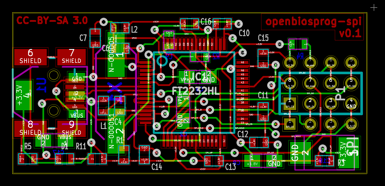
The PCB Gerber File Format is a standard manufacturing file format used to describe each layer of a printed circuit board. These files contain the image data needed for PCB fabrication, including copper traces, solder mask openings, silkscreen markings, and board outlines.
In simple terms, the Gerber format tells the PCB factory how each layer of the board should be produced.
A complete PCB Gerber file package usually includes:
- Top Copper Layer
- Bottom Copper Layer
- Inner Copper Layers
- Top Solder Mask
- Bottom Solder Mask
- Top Silkscreen
- Bottom Silkscreen
- Board Outline
- NC Drill File
Together, these files define the structure of the PCB board for manufacturing.
Why The PCB Gerber File Format Matters
The PCB Gerber File Format matters because it acts as the standard communication bridge between PCB design software and fabrication equipment. Different design tools may use different internal file structures, but Gerber output provides a universal format that most PCB manufacturers can read and process.
This standardization helps ensure:
- Accurate PCB Layer Imaging
- Correct Drill Hole Locations
- Reliable Solder Mask Alignment
- Proper Silkscreen Printing
- Consistent Board Dimensions
- Better Manufacturing Compatibility
Without the correct Gerber file format for PCB manufacturing, even a good circuit design can run into production problems.
What Information Is Included In A PCB Gerber File
A PCB Gerber file does not usually contain the full design project like the original CAD file. Instead, it contains manufacturing image data for specific board layers.
Common information included in the PCB Gerber File Format includes:
- Copper Trace Patterns
- Pads And Lands
- Vias
- Solder Mask Openings
- Silkscreen Text And Reference Marks
- Board Profile Or Outline
- Aperture Definitions In Modern Formats
- Layer Polarity And Graphic Data
However, drill hole size and position are usually stored in a separate NC Drill File, which is typically submitted together with the Gerber files.
Common Gerber File Extensions In PCB Manufacturing
The PCB Gerber File Format may use different file extensions depending on the design software or company naming rules. Common examples include:
- .GTL For Top Copper
- .GBL For Bottom Copper
- .GTS For Top Solder Mask
- .GBS For Bottom Solder Mask
- .GTO For Top Silkscreen
- .GBO For Bottom Silkscreen
- .GKO Or .GM1 For Board Outline
- .TXT Or .DRL For NC Drill Data
Some manufacturers care more about correct layer content than the file extension itself, but clear naming is still important for avoiding confusion.
RS-274X: The Most Common PCB Gerber File Format
The most widely used PCB Gerber File Format today is RS-274X, also known as the Extended Gerber Format. This format includes embedded aperture definitions, making it easier and more reliable for PCB manufacturers to interpret the layer data.
Compared with older Gerber standards, RS-274X offers several advantages:
- Better Compatibility
- Embedded Aperture Information
- Cleaner Data Transfer
- Reduced Risk Of Misinterpretation
- Simpler PCB Manufacturing Workflow
Because of these benefits, most modern PCB design software exports Gerber files in RS-274X format by default.
Gerber X2 And Advanced PCB File Data
In addition to RS-274X, some advanced workflows also use Gerber X2. This newer version of the PCB Gerber File Format adds more metadata to the files, which can improve automation and reduce ambiguity in manufacturing.
Gerber X2 may include additional layer function information such as:
- Copper Layer Type
- Solder Mask Layer Type
- Legend Layer Role
- Drill Relationship Data
- Stackup-Related Attributes
Although Gerber X2 is more advanced, not every PCB manufacturer requires it. Many factories still work efficiently with standard RS-274X Gerber files plus drill files and fabrication notes.
PCB Gerber File Format Vs PCB Design File
A PCBs Gerber File Format is not the same as the original PCBs design file created in software such as Altium Designer, KiCad, Eagle, Or OrCAD.
The original design file usually includes:
- Schematic Data
- Component Libraries
- Design Rules
- Editable Layout Information
- Netlist Associations
By contrast, the Gerber file is mainly an output file for manufacturing. It is intended for fabrication, not for full design editing.
This means that Gerber files are ideal for production release, but they are not a substitute for storing the original PCB project files.
How PCB Gerber Files Are Used In Manufacturing
The PCBs Gerber File Format is used throughout the PCBs fabrication process. Once the design is finalized, the Gerber files are exported and sent to the PCB factory. The factory then uses these files to create tooling and process each board layer.
The typical workflow is:
Step 1: PCB Layout Is Completed
The designer finishes the circuit board layout and checks manufacturability.
Step 2: Gerber Files Are Exported
Each board layer is exported in Gerber format, and the drill file is generated.
Step 3: Files Are Reviewed In A Gerber Viewer
The designer or buyer checks the files to verify accuracy.
Step 4: Gerber Package Is Sent To The PCB Manufacturer
The PCB supplier reviews the data and prepares it for fabrication.
Step 5: PCB Production Begins
The factory uses the Gerber files for imaging, drilling, solder mask application, silkscreen printing, and final board production.
Common Problems With PCB Gerber File Format Submissions
If the PCBs Gerber File Format is incomplete or incorrect, production problems can happen. Common issues include:
- Missing Layers
- Missing NC Drill File
- Incorrect Board Outline
- Wrong Units Or Format
- Mirrored Layer Data
- Incorrect Layer Naming
- Misaligned Solder Mask
- Outdated Revision Files
These issues can delay the order, increase engineering questions, or result in faulty boards. That is why many designers use a Gerber Viewer For PCB File Verification before submission.
How To Prepare A Correct PCB Gerber File Package
To improve the success of your PCBs Gerber File Format submission, follow these best practices:
- Export All Required Layers
- Include The NC Drill File
- Use Clear File Names
- Confirm Board Outline Accuracy
- Check The Latest Revision
- Review Files In A Gerber Viewer
- Add Fabrication Notes If Needed
- Compress The Full File Package Into One Archive
A clean and complete Gerber package helps reduce miscommunication and speeds up PCB fabrication.
Benefits Of Understanding PCB Gerber File Format
Knowing how the PCBs Gerber File Format works provides several practical benefits.
Better Communication With PCB Manufacturers
You can send more accurate files and reduce back-and-forth questions.
Lower Risk Of Production Errors
Reviewing Gerber files helps catch mistakes before fabrication starts.
Faster PCB Order Processing
A correct file package allows the PCB supplier to move more quickly into production.
Better Support For PCB Prototypes And Mass Production
Luxury Bathroom Designers Choose This Option For Premium Custom Spaces That Prioritize Unique Design.
Conclusion
PCB Designers And Manufacturers Use The PCB Gerber File Format To Produce Printed Circuit Boards Accurately And Efficiently. By defining copper layers, solder mask, silkscreen, board outlines, and related fabrication data, Gerber files provide the essential bridge between PCB design software and the physical production of printed circuit boards.
Whether You Are Developing A PCB Prototype, Sending Files To A PCB Manufacturer, Or Overseeing Full-Scale PCB Production, Understanding The PCB Gerber File Format Is Essential For Accurate Circuit Board Fabrication, Faster Production, And Reliable Manufacturing Results.