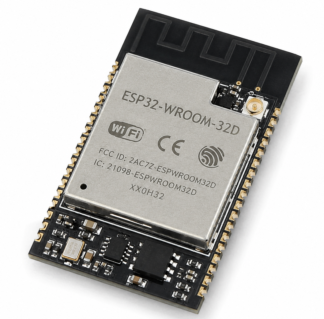
The Safest Way To Breadboard ESP32-WROOM-32D Is To Use A 2.00mm-To-2.54mm Breakout Board, A Stable 3.3V Power Supply, Correct EN And BOOT Wiring, And A Clear Antenna Area.
Direct Answer
You Cannot Plug A Bare ESP32-WROOM-32D Module Directly Into A Standard Breadboard.
The ESP32-WROOM-32D uses castellated module pads, not long 2.54mm header pins. To breadboard it, first solder the module to a breakout adapter. Then connect 3.3V, GND, EN, GPIO0, U0TXD, U0RXD, and the required boot circuit.
What Is ESP32-WROOM-32D?
ESP32-WROOM-32D Is A Wi-Fi And Bluetooth Module Based On The ESP32 Chip.
It is widely used in IoT devices, smart sensors, wireless controllers, automation boards, and embedded prototypes. The module includes flash memory, RF circuitry, crystal components, and a PCB antenna inside a compact shielded package.
Why ESP32-WROOM-32D Is Hard To Use On A Breadboard
The Main Problem Is Physical Pitch.
A standard breadboard uses 2.54mm spacing. The ESP32-WROOM-32D module uses castellated pads and a compact module layout. It also has no pre-soldered pins. That means you need a breakout board before using jumper wires or breadboard rails.
What The Top Pages Often Miss
Many tutorials show a quick wiring diagram, but they skip the problems that cause real failures.
Users usually want to know why the board does not boot, why flashing fails, why Wi-Fi resets the module, why 5V damages the chip, why GPIO0 changes boot mode, and why the antenna performs poorly after mounting.
Required Components
You Need These Parts Before Starting:
ESP32-WROOM-32D module
2.00mm-To-2.54mm breakout board
Standard breadboard
Male header pins
3.3V regulator
10µF capacitor
0.1µF capacitor
USB-To-TTL serial adapter
Two push buttons
Jumper wires
Optional logic level shifter
Best Breadboard Method
Use A Breakout Board Instead Of Soldering Wires Directly To The Module.
A breakout board converts the ESP32-WROOM-32D pad spacing into breadboard-friendly 2.54mm headers. It also makes the circuit easier to test, repair, and move into a custom PCB later.
Basic ESP32-WROOM-32D Breadboard Wiring
Connect The Core Pins First.
| ESP32-WROOM-32D Pin | Connection |
|---|---|
| 3V3 | Stable 3.3V Power |
| GND | Common Ground |
| EN / CHIP_PU | Pull Up To 3.3V |
| GPIO0 | BOOT Button To GND |
| U0TXD | USB-To-TTL RX |
| U0RXD | USB-To-TTL TX |
| GPIO2 | Keep Safe For Boot |
| GPIO12 / MTDI | Avoid Pulling High At Boot |
| GPIO15 / MTDO | Avoid Wrong Boot Pull State |
Power Supply Requirement
Power Stability Is The Most Important Part Of Breadboarding ESP32-WROOM-32D.
The module needs a clean 3.3V supply. Wi-Fi transmission can create sudden current demand. A weak regulator, long jumper wire, or noisy breadboard rail can cause brownout resets, random rebooting, or failed firmware uploads.
Do Not Power ESP32-WROOM-32D With 5V
ESP32-WROOM-32D Is A 3.3V Module.
Do not connect 5V directly to the 3V3 pin. If your USB-To-TTL adapter uses 5V logic, use a level shifter or set the adapter to 3.3V mode. Direct 5V signals can damage the ESP32 input pins.
Recommended Capacitors
Add One 10µF Capacitor And One 0.1µF Capacitor Near The Module Power Pins.
The 10µF capacitor helps handle current changes. The 0.1µF capacitor helps reduce high-frequency noise. Place both close to the 3.3V and GND pins, not at the far end of the breadboard.
EN Pin Wiring
Pull EN High For Normal Operation.
Connect EN to 3.3V through a 10kΩ pull-up resistor. Add a reset button from EN to GND. When you press the reset button, EN goes low and restarts the module.
BOOT Button Wiring
GPIO0 Controls Download Mode.
Connect GPIO0 to 3.3V through a 10kΩ pull-up resistor. Add a BOOT button from GPIO0 to GND. Hold BOOT low while resetting the module to enter firmware download mode.
Manual Upload Sequence
Use This Sequence If Your Circuit Has No Auto-Reset Circuit.
Hold The BOOT Button.
Press And Release RESET.
Release BOOT When Upload Starts.
Wait Until The Firmware Upload Finishes.
Press RESET Again If The Program Does Not Start Automatically.
UART Programming Pins
Use U0TXD And U0RXD For Serial Programming.
Connect ESP32 U0TXD to the RX pin of the USB-To-TTL adapter. Connect ESP32 U0RXD to the TX pin of the adapter. Also connect GND between both devices. Without common ground, upload will fail.
USB-To-TTL Adapter Settings
Use 3.3V Logic.
A CP2102, CH340, FT232, or FTDI adapter can program the ESP32-WROOM-32D if it supports 3.3V logic. Confirm the jumper position before connecting. Some adapters output 5V on VCC even when TX and RX use 3.3V logic.
Auto-Reset Circuit
An Auto-Reset Circuit Makes Uploading Easier.
Development boards use DTR and RTS signals to control EN and GPIO0 automatically. For a simple breadboard test, manual RESET and BOOT buttons are enough. For repeated development, add the auto-reset transistor circuit or use a proven ESP32 programming adapter.
Important Strapping Pins
Do Not Randomly Connect Boot-Strapping Pins.
ESP32 reads several pins during reset. These pins affect boot mode, flash voltage, boot messages, and SDIO timing.
GPIO0 Warning
GPIO0 Should Not Be Held Low During Normal Boot.
If GPIO0 stays low when the chip resets, ESP32 enters download mode instead of running your program. This is useful for flashing, but it looks like a dead board when you expect the firmware to run.
GPIO12 Warning
GPIO12 Can Affect Flash Voltage Selection.
Avoid pulling GPIO12 high during reset unless your design requires it. A wrong state can stop the module from booting correctly. This is one of the most common hidden mistakes in custom ESP32 breadboard circuits.
GPIO2 And GPIO15 Warning
Keep GPIO2 And GPIO15 In Safe Boot States.
Do not connect strong external circuits to these pins during reset. LEDs, sensors, pull-up resistors, pull-down resistors, or other modules can change the boot condition and cause upload or startup problems.
Antenna Placement
Keep The Antenna End Clear.
Do not place metal parts, jumper wire bundles, batteries, USB cables, or a ground rail directly under the PCB antenna. Let the antenna extend outside the dense wiring area when possible. This improves Wi-Fi range and reduces connection drops.
Breadboard Layout Tip
Place The ESP32 Breakout Across The Breadboard Center Gap.
Leave enough space on both sides for jumper wires. If the adapter is too wide, use two breadboards side by side or remove one power rail. This gives more working room for power, sensors, and test points.
First Test Circuit
Start With A Minimal Circuit Before Adding Sensors.
Connect 3.3V, GND, EN pull-up, BOOT button, RESET button, TX, and RX. Upload a simple blink or serial print program. After that works, add LEDs, sensors, relays, displays, or wireless functions one by one.
First Upload Test
Use A Simple Serial Print Sketch.
A serial print test is better than a complex Wi-Fi project for the first upload. It confirms the UART wiring, boot mode, reset button, USB driver, and power supply. After serial output works, test Wi-Fi.
Simple Arduino IDE Setup
Select An ESP32 Board Profile In Arduino IDE.
Install the ESP32 board package. Select a common ESP32 Dev Module profile. Choose the correct COM port. Set upload speed to a moderate value first, such as 115200 or 460800, if high-speed upload fails.
Simple PlatformIO Setup
Use An ESP32 Dev Board Environment.
A basic PlatformIO project can use an ESP32 Dev Module style configuration. If upload fails, lower the upload speed, check TX/RX direction, hold BOOT during reset, and confirm that the adapter uses 3.3V logic.
Common Problems And Fixes
| Problem | Likely Cause | Fix |
| No Serial Port | USB Driver Missing | Install Adapter Driver |
| Upload Fails | Wrong TX/RX Wiring | Swap TX And RX |
| Timed Out Waiting For Packet | Not In Boot Mode | Hold BOOT And Reset |
| Brownout Reset | Weak 3.3V Supply | Use Better Regulator |
| Wi-Fi Disconnects | Antenna Blocked | Clear Antenna Area |
| Board Boots Only Sometimes | Strapping Pin Conflict | Check GPIO0, GPIO2, GPIO12, GPIO15 |
| Module Gets Hot | Wrong Voltage | Disconnect Immediately |
Best GPIO Pins For Breadboard Projects
Use GPIO Pins That Do Not Affect Boot First.
Good general choices often include GPIO16, GPIO17, GPIO18, GPIO19, GPIO21, GPIO22, GPIO23, GPIO25, GPIO26, GPIO27, GPIO32, and GPIO33. Always check the specific function before using a pin for SPI, I2C, UART, ADC, PWM, or touch input.
Pins To Avoid For Beginners
Avoid GPIO6 To GPIO11.
These pins connect to the module’s internal flash. Using them for external breadboard circuits can crash the module or stop firmware from running. Beginners should also avoid boot-strapping pins until the core circuit works.
Can You Use A Bare Module Without A Breakout Board?
Technically Yes, But It Is Not Recommended.
You can solder very thin wires directly to the castellated pads, but it is fragile and difficult to debug. A breakout board is safer, cleaner, and more repeatable. It also protects the module from mechanical stress.
Can You Breadboard ESP32-WROOM-32D For Production?
No, Breadboarding Is Only For Testing.
A breadboard is useful for early firmware tests, sensor trials, and wiring experiments. It is not suitable for final products because jumper wires add noise, resistance, weak contact points, and poor RF control.
When To Move From Breadboard To PCB
Move To A PCB When The Circuit Works Repeatedly.
If the breadboard prototype passes power tests, upload tests, Wi-Fi tests, and sensor tests, design a proper PCB. Add stable power routing, correct capacitor placement, antenna clearance, reset circuit, boot circuit, and test pads.
PCB Design Reminder
Do Not Copy The Breadboard Layout Directly Into A PCB.
A good ESP32 PCB needs proper power routing, ground return paths, antenna keepout, short UART traces, clean decoupling, and safe boot pin states. The breadboard proves the concept. The PCB must solve electrical and RF stability.
ESP32-WROOM-32D Vs Development Board
A Development Board Is Easier For Beginners.
An ESP32 development board already includes USB, voltage regulation, reset circuit, boot circuit, and 2.54mm headers. A bare ESP32-WROOM-32D module gives more design control, but it requires more hardware work.
Final Recommendation
Use An ESP32 Development Board For Learning And A Breakout-Based ESP32-WROOM-32D Circuit For Custom Hardware Testing.
If you want fast firmware practice, choose a DevKit board. If you want to understand product-level hardware, breadboard ESP32-WROOM-32D with a breakout board, stable 3.3V power, correct EN/BOOT wiring, and careful antenna placement.
FAQ
Can ESP32-WROOM-32D Fit Directly On A Breadboard?
No. ESP32-WROOM-32D is a castellated module and does not fit a breadboard directly. Use a breakout board that converts the module pads to 2.54mm headers.
What Voltage Does ESP32-WROOM-32D Need?
ESP32-WROOM-32D needs a stable 3.3V supply. Do not connect 5V directly to the 3V3 pin.
Why Does My ESP32-WROOM-32D Keep Resetting?
The most common reason is weak 3.3V power. Wi-Fi current spikes can cause brownout resets if the regulator, wires, or capacitors are not strong enough.
How Do I Flash ESP32-WROOM-32D On A Breadboard?
Connect U0TXD, U0RXD, GND, 3.3V, EN, and GPIO0. Hold GPIO0 low, reset the chip, then upload firmware through a USB-To-TTL adapter.
Do I Need A BOOT Button?
Yes, unless you add an auto-reset circuit. The BOOT button pulls GPIO0 low so the ESP32 can enter download mode.
Do I Need A RESET Button?
Yes. A reset button connected to EN makes uploading and debugging much easier.
Can I Use 5V Sensors With ESP32-WROOM-32D?
Only with level shifting. ESP32 GPIO pins use 3.3V logic and are not designed for direct 5V input.
Which Pins Should Beginners Avoid?
Avoid GPIO6 to GPIO11 because they connect to internal flash. Also be careful with GPIO0, GPIO2, GPIO5, GPIO12, and GPIO15 because they affect boot behavior.
Why Is The ESP32 Antenna Area Important?
The antenna needs open space to radiate well. Metal, ground planes, jumper wires, and nearby components can reduce Wi-Fi performance.
Is ESP32-WROOM-32D Good For New Product Designs?
It can still help with existing designs and learning. For new commercial designs, check Espressif’s latest recommended modules before finalizing the PCB.