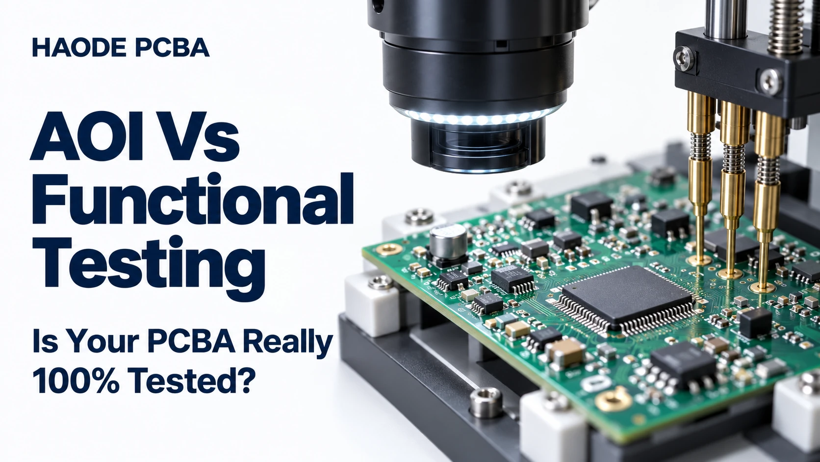
AOI vs functional testing is a comparison between checking visible assembly features and measuring how a powered PCBA behaves. Neither method alone proves that every possible defect has been excluded. A useful quotation identifies the checks performed, the boards tested, the acceptance limits and the records supplied.
If a supplier promises “100% tested,” ask: 100% of which boards, tested for which requirements, under what conditions? Every board may receive an optical inspection while only selected boards receive a powered test.
This article focuses on reviewing production-test scope before placing an order. Use the tables below as proposed buyer worksheets, not as universal test specifications or claims about a particular factory
AOI Vs Functional Testing: What Is The Difference?
Automated optical inspection (AOI) evaluates visible features against an inspection program. Functional testing (FCT) powers the assembly and checks selected behavior using defined inputs, loads and measurements.
| Question | AOI | Functional Testing |
|---|---|---|
| What does it evaluate? | Visible assembly features, including placement and accessible solder geometry | Electrical behavior exercised by the test sequence |
| Does it establish correct firmware? | No | Only if firmware identity or relevant behavior is checked |
| Does it prove operation under load? | No | Only at the loads and conditions included |
| Can it check hidden BGA solder geometry? | Not the concealed joints themselves | It may detect an electrical symptom, but does not image the joint |
| What determines coverage? | Visibility, equipment, inspection program and review criteria | Access, stimuli, loads, measurements, software and limits |
| What should the buyer request? | Inspection scope and exception handling | Test specification and example result record |
The practical difference is the evidence produced. A visible solder bridge and an output that collapses under load require different checks. Therefore, select methods around failure risks rather than treating one machine name as a complete quality plan.
What Does “100% Tested” Actually Tell You?
The phrase is incomplete until the supplier defines its denominator and procedure.
Separate four questions:
- Unit coverage: Does every shipped board undergo this check, or only a sample?
- Requirement coverage: Which functions, connections or defect categories does it address?
- Condition coverage: At which input voltage, load, temperature and operating state?
- Record coverage: Can the result be linked to an individual board or only a batch?
Consider an illustrative batch of 200 controller boards. All 200 receive AOI, but only five undergo a relay-load test. The supplier can accurately state that every board received AOI. That does not establish that every board passed the relay-load test.
Likewise, 200 boards that each pass a startup check have not necessarily been checked in sleep mode, at maximum specified load or during communication.
Ask the supplier to list inspection and test stages separately in the PCB assembly quote. Avoid accepting a single “testing included” line without an attached scope.
Which Failures Can An AOI Pass Leave Unresolved?
A Correct-Looking Component May Have The Wrong Electrical Value
Parts with similar packages may look alike. A readable marking can help an inspection program identify some mismatches, but do not assume that optical inspection establishes every resistance, capacitance or semiconductor variant.
For a value-sensitive circuit, ask how the particular part is verified: material controls, an accessible electrical measurement, or a functional response that actually distinguishes the wrong value.
An output test that passes with several possible component values may not establish that the intended value was fitted.
Hidden Solder Joints Need A Different Inspection Approach
BGA solder joints sit beneath the package. OMRON’s technical discussion of automated X-ray inspection explains the challenge of visually inaccessible joints and the differences between transmission and CT imaging.
Where hidden joints matter, define the relevant PCB X-ray inspection scope: packages, defect criteria, inspection method and sampling or every-unit inspection.
An X-ray result and a functional result answer different questions. Neither should be presented as a universal substitute for the other.
Assembly Appearance Does Not Establish Product Configuration
A board may look correct while containing an outdated firmware image, incorrect calibration data or an unassigned identifier.
If configuration matters to shipment acceptance, add explicit verification. State whether the station checks the application version, programmed-image integrity, configuration values or device-specific data.
Do not rely only on a version string when the requirement is to verify the complete programmed image; choose a verification method appropriate to the device and its protection settings.
What Can Functional Testing Still Miss?
Functional testing validates only what the sequence exercises and observes.
A controller that starts successfully may still have an untested input channel. A memory device may return its identity correctly while a larger address range remains untested. A communications port may exchange a short message without establishing performance at the intended data rate.
For each important function, ask: What input forces this function to operate, and what measurement would reveal a failure?
A useful PCBA functional testing specification describes both. “Check communication” is incomplete; naming the interface, test partner, settings, exchange and acceptance criteria makes the requirement reviewable.
Production FCT also does not automatically establish long-term reliability, environmental durability or regulatory compliance. Those require their own justified validation or qualification activities. Where the product needs them, define environmental testing separately from the routine production sequence.
Build An AOI Vs Functional Testing Coverage Matrix
The following example assumes a low-voltage controller with a power input, memory, digital inputs, switched outputs and a communication port. Adapt it to the actual schematic and product requirements.
| Buyer Concern | Check To Specify | Important Boundary |
|---|---|---|
| Will the board start correctly? | Controlled startup with defined power conditions and startup indication | One successful boot does not cover every power sequence |
| Is the supply operating correctly? | Measure selected rails and input current in named operating states | Limits depend on input, load and state |
| Is the intended firmware installed? | Approved image/configuration verification | Application identification alone may be insufficient |
| Does external memory work? | Approved write/read test in a safe test region | Do not overwrite calibration, boot or customer data |
| Do all input channels respond? | Apply defined stimuli to each required channel | A shared status indicator can hide an untested channel |
| Can outputs drive their intended load? | Exercise specified outputs with approved loads | An unloaded voltage reading is not a load test |
| Does the interface communicate? | Exchange defined messages using stated settings | A loopback may omit the connector, cable or external interface path |
| Are hidden joints acceptable? | Suitable inspection of named packages | Electrical operation does not reveal all joint geometry |
For an AOI vs functional testing review, add an owner and evidence requirement to each row. If a check is omitted, record the gap and the reason rather than allowing it to disappear from the quotation.
Distinguish A Simulated Input From A Real Sensor Check
Injecting a voltage at an ADC input can test part of the signal path. It does not necessarily test the sensor, its connector or the upstream conditioning circuit.
Similarly, a software-generated sensor value may validate message formatting while bypassing the measurement hardware entirely.
Write down where the stimulus enters and where the response is observed. This makes the boundary of the test visible to procurement and engineering.
How Should Pass/Fail Limits Be Set?
Use approved product requirements and an assessment of the measurement setup. A convenient round number or one reference board’s reading is not an adequate basis by itself.
For illustration only, suppose an approved rail requirement is 3.30 V ±5% under specified conditions. The product interval is 3.135–3.465 V. Those numbers do not automatically become the tester’s release limits.
Engineering still needs to consider instrument uncertainty, fixture voltage drop, measurement location and repeatability. Decide whether a guard band or another decision rule is needed before production; do not improvise it after a borderline result.
Keysight’s technical overview of component tolerances and ICT test limits discusses tolerance analysis for in-circuit measurements. Its scope is ICT, but it reinforces why component tolerances and the measurement path must be considered when establishing those limits.
For each measured parameter, document:
- Test point, instrument and units.
- Supply, load and operating state.
- Stabilization time and measurement method.
- Lower and upper limits, including the boundary rule.
- Action for unstable readings or failed measurements.
Never widen a limit merely to make a failing batch pass. Investigate whether the cause is the product, the fixture, the method or an incorrectly specified requirement.
Where Do ICT And Flying Probe Fit?
AOI vs functional testing is not the entire test strategy. Electrical structural tests can add evidence about assembly connections and component values.
Keysight’s manufacturing-test overview distinguishes in-circuit capabilities from functional measurements, while also describing platforms that combine methods. The label on a station therefore does not fully describe its programmed coverage.
Ask which nets and components the proposed in-circuit testing program can access and evaluate. Parallel circuitry, physical access and device behavior can limit particular measurements.
If the supplier proposes flying probe, request the same coverage explanation rather than assuming “fixtureless” means either complete coverage or inadequate coverage. Review the actual program and access requirements.
Where access is missing, a design-for-testability review can identify changes before the next board revision. Avoid discovering after assembly that a critical measurement has no practical connection point.
What Happens When A Board Fails And Then Passes?
Define retest rules before the first production lot.
If a board fails, passes after reconnecting the fixture, and ships with only the final PASS recorded, useful evidence has been lost. The cause could be contact instability, an intermittent assembly fault or another unresolved issue.
A proposed workflow is to preserve the initial failure, investigate within the agreed procedure, record any repair or fixture action, and run the required retest sequence. Escalate unexplained repeated failures according to the approved disposition rules.
Request first-pass results separately from final accepted results. A final pass rate alone does not show how much repair or retesting occurred.
For traceable orders, agree records such as board serial number, test-program revision, firmware identity, timestamp, relevant measurements, failure codes and repair/retest history. Confirm the required PCBA traceability level before approving the format.
AOI Vs Functional Testing: Compare The Quoted Scope
Compare the defined work, not the testing charge alone.
| Quote Item | Clarification To Request |
|---|---|
| Development charge | Which fixture, software and documentation are delivered? |
| Per-board testing | Which sequence is included on every unit? |
| External loads or instruments | Are they supplied, rented, reused or charged separately? |
| Failures and retests | What troubleshooting and repair work is included? |
| Revision changes | What triggers fixture or program revalidation and additional cost? |
| Result records | Which data are retained, delivered and linked to each board? |
A short startup check and a multi-channel loaded test may both be called FCT. Their prices are not comparable until their scopes are comparable.
You can adapt this RFQ request:
Please quote AOI and electrical/functional testing separately. For each stage, identify the checks, unit coverage, test conditions, acceptance limits and known exclusions. Separate fixture and software development from recurring test charges. Include an example result record and describe failure handling, retesting and revision control.
For an enquiry to Haode PCBA, provide the assembly files, schematic, approved firmware, interface details, operating requirements and expected order quantity. Identify the failures that would matter most in your application and request a proposed coverage matrix for engineering review.
The useful outcome of an AOI vs functional testing comparison is a test plan you can audit: which requirement was checked, under which conditions, on which board, and with what result.