
Related Keywords: microvia reflow test, via chain continuity test, IPC-TM-650 2.6.27B, IPC D coupon, microvia resistance monitoring, latent microvia failure, open-reconnect defect, HDI PCB reliability testing
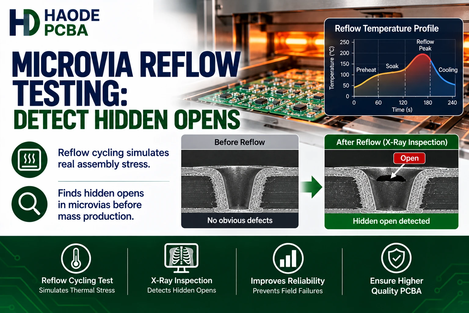
Microvia reflow testing detects interconnections that open only while the PCB is hot and reconnect after cooling. A conventional final electrical test can miss these latent defects because it normally checks continuity at room temperature rather than monitoring resistance throughout the reflow cycle.
The most useful method combines a representative via-chain coupon, a controlled convection-reflow profile, and continuous resistance measurement. Therefore, buyers should not accept “passed electrical test” as complete evidence for complex stacked microvias.
The central question is:
Does the microvia remain electrically stable while thermal expansion places maximum stress on its interfaces?
Our PCB microvia reliability article explains the underlying interface failures. This article focuses on how to expose them before production boards reach assembly or field service.
What Is Microvia Reflow Testing?
Microvia reflow testing passes a representative PCB coupon through repeated convection-reflow cycles while the test system measures electrical resistance.
The coupon contains a daisy chain of production-representative vias. Therefore, current must pass through many microvia interfaces before returning to the measurement equipment.
A typical test sequence includes:
- Condition the test coupon.
- Attach measurement leads and thermocouples.
- Establish the resistance reference.
- Run a controlled convection-reflow profile.
- Record resistance throughout heating and cooling.
- Repeat the required number of cycles.
- Identify resistance changes, intermittent opens, or complete failures.
- Perform physical analysis when necessary.
The objective is not simply to heat the coupon. Instead, the test must connect temperature, time, and electrical behavior.
Why Does Final Electrical Testing Miss Microvia Failures?
Bare-board electrical testing usually detects:
- Permanent open circuits
- Short circuits
- Incorrect net connections
- Excessive resistance at the test temperature
However, some microvia interfaces behave differently when heated.
Open-Reconnect Behavior
A weak interface may remain closed at room temperature. As the PCB heats, the dielectric expands and pulls the interface apart. Resistance then increases sharply or the circuit opens.
During cooling, the materials contract. The fractured surfaces may touch again, allowing the coupon to recover its original continuity.
Consequently, the board can:
- Pass electrical testing before reflow
- Open near the peak reflow temperature
- Reconnect after cooling
- Pass another room-temperature test
- Fail intermittently in the assembled product
IPC has warned that weak interfaces between microvia target pads and electrolytic copper fill can produce latent reliability problems, particularly in stacked structures.
Pass-Fail Testing Captures Only One Moment
A flying-probe or fixture test provides a measurement at a specific temperature and time. In contrast, Microvia Reflow Testing observes the interconnection throughout the period when thermal stress changes most rapidly.
Therefore, the two tests answer different questions:
| Test | Primary Question |
|---|---|
| Final Bare-Board Electrical Test | Is the connection open or shorted now? |
| Before-And-After Resistance Test | Did permanent resistance change remain after reflow? |
| Continuous Reflow Monitoring | Did the connection become unstable at any point during heating or cooling? |
| Long-Term Thermal Cycling | How does the interconnection degrade over repeated service-related stress? |
A board may pass the first two tests and still fail continuous monitoring.
How Does A Via-Chain Coupon Work?
A via-chain coupon connects multiple test structures in series. Because each microvia adds another interface to the chain, a resistance change anywhere in the chain affects the measured circuit.
This approach increases the probability of detecting a process-related weakness. However, the coupon must represent the production PCB.
A useful coupon should reproduce:
- Microvia start and stop layers
- Stacked or staggered construction
- Number of stacked levels
- Microvia diameter
- Dielectric depth
- Target- and capture-pad dimensions
- Copper filling
- Cap copper
- Blind and buried via transitions
- Sequential lamination history
- Ground and power plane interaction
- Production materials
- Production panel processing
IPC-TM-650 2.6.27B states that propagated B and D coupons should contain the intended via structures. It also requires representative blind, buried, filled, and microvia structures when applicable.
Therefore, a generic coupon with one simple microvia cannot qualify a PCB containing several different stacked and staggered structures.
The stacked vs staggered microvias comparison explains why each architecture needs separate consideration.
What Does IPC-TM-650 2.6.27B Require?
IPC-TM-650 Method 2.6.27B covers thermal stress through convection-reflow assembly simulation.
Important test elements include:
| Test Element | IPC-TM-650 2.6.27B Requirement |
|---|---|
| Coupon Type | Applicable IPC-2221 Appendix A or B coupon, including D coupon |
| Conditioning | Minimum six hours at 105–125°C unless otherwise agreed |
| Reflow Profiles | Defined nominal 230°C, 245°C, or 260°C profiles |
| Minimum Reflow Cycles | Six |
| Resistance Sampling | At least one reading per test net per second |
| Resistance Reference | First cycle’s peak-temperature resistance |
| Default Acceptance | Maximum 5% resistance change unless otherwise specified |
| Post-Test Evaluation | Resistance evaluation and/or applicable microsection inspection |
| Deviations | Agreed between user and supplier |
These values should not be copied blindly into every purchase drawing. The selected temperature profile should reflect the intended assembly process, material system, and applicable product requirements.
For example, a product assembled with a lower-temperature solder system may not need the same profile as a conventional lead-free assembly. Conversely, a high-reliability product may need additional cycling after reflow simulation.
The official method requires the test system to take at least one resistance reading from each sample net every second during the complete cycle. It also defines six reflow cycles as the minimum unless the user and supplier agree otherwise.
Why Is Continuous Resistance Monitoring Important?
Continuous monitoring reveals when the electrical change occurs.
Normal Thermal Resistance Change
Copper resistance naturally increases with temperature. Therefore, a hot coupon will not have the same resistance as a cool coupon.
The test system must distinguish this expected temperature coefficient from structural damage.
A smooth and repeatable resistance-temperature curve usually indicates normal conductor behavior. In contrast, sudden steps, spikes, excessive drift, or complete opens can indicate interconnect instability.
Typical Resistance Signatures
| Resistance Pattern | Possible Interpretation | Buyer Action |
|---|---|---|
| Smooth Increase During Heating And Recovery During Cooling | Normal temperature-dependent behavior | Compare cycles for repeatability |
| Sudden Resistance Spike Near Peak Temperature | Temporary interface separation | Treat as potential open-reconnect defect |
| Increasing Peak Resistance In Each Cycle | Progressive crack growth or interface degradation | Continue analysis and isolate structure |
| High Resistance Remains After Cooling | Permanent damage | Reject or investigate |
| Complete Open During Heating, Then Recovery | Mechanically switching interface | Immediate failure investigation |
| Irregular Noise At Similar Temperatures | Unstable contact, connection, or measurement setup | Verify test leads, then repeat under control |
| Similar Failure Across Several Coupons | Systematic process or design problem | Review manufacturing lot and structure |
| One Isolated Failure | Localized defect or sampling indication | Investigate before dismissing as an outlier |
The testing equipment must also have enough accuracy to distinguish a true resistance change from measurement uncertainty.
IPC-TM-650 2.6.27B limits total system uncertainty to less than 10% of the selected failure criterion. For example, a 5% failure limit requires substantially better system accuracy than a simple handheld continuity check.
Why Should Resistance Use A Peak-Temperature Reference?
Comparing a hot resistance value directly with a room-temperature value can produce misleading results because copper resistance changes normally with temperature.
IPC-TM-650 2.6.27B uses the first cycle’s peak-temperature resistance as the reference for performance-based D-coupon evaluation. Therefore, later peak-temperature readings can be compared under similar thermal conditions.
This approach helps separate:
- Expected copper temperature response
- Coupon-to-coupon baseline differences
- Permanent resistance growth
- Heat-activated interface separation
- Cycle-to-cycle degradation
However, the first cycle is not proof of a defect-free structure. It establishes the comparison reference. The complete resistance record still matters because an abnormal event may occur within any cycle.
Which Reflow Profile Should Buyers Specify?
The profile should represent the thermal stress that the PCB will experience during assembly.
IPC-TM-650 2.6.27B provides nominal 230°C, 245°C, and 260°C profiles. Its default profile uses a nominal target of 260°C, while alternate profiles address lower-temperature conditions.
The buyer should consider:
- Solder alloy
- Actual component-temperature limits
- PCB material
- Board thickness
- Copper distribution
- Assembly thermal mass
- Number of SMT sides
- Expected rework
- Product reliability class
The coupon surface temperature—not merely the oven setpoint—must follow the defined profile. Therefore, the test laboratory should attach and document thermocouples correctly.
A production PCB reflow soldering profile and a coupon reliability profile serve related but different purposes. The assembly profile forms acceptable solder joints, while the reliability test applies a repeatable thermal stress to evaluate the bare-board interconnections.
Are Six Reflow Cycles Always Enough?
Six cycles provide the minimum specified by IPC-TM-650 2.6.27B. However, they do not represent a universal lifetime guarantee.
The appropriate test sequence depends on the purpose.
Qualification Testing
Qualification asks whether a design and manufacturing process can produce a stable structure.
It may include:
- Six-cycle reflow simulation
- Continuous resistance monitoring
- Additional thermal cycling
- IST
- Microsectioning
- Statistical comparison across several panels
- Failure analysis
First-Article Testing
First-article testing confirms that the released design, selected supplier, materials, and manufacturing flow work together.
The test should include all production microvia structures and representative panel locations.
Lot-Acceptance Testing
Lot acceptance screens production output against defined criteria. Therefore, it requires an agreed number of coupons, panels, and test frequency.
Process-Change Validation
A manufacturer should evaluate whether changes to material, plating chemistry, laser parameters, lamination, via geometry, or process location require requalification.
| Test Purpose | Main Question |
|---|---|
| Initial Qualification | Can this design and process produce reliable microvias? |
| First Article | Does this released PCB meet the approved requirements? |
| Lot Acceptance | Does this production lot remain within the qualified process? |
| Change Validation | Did a material or process change alter reliability? |
| Failure Investigation | Which interface failed and under what thermal condition? |
Consequently, “six cycles passed” should always include the coupon design, profile, resistance data, sampling plan, and acceptance criterion.
How Does Microvia Reflow Testing Compare With IST?
Microvia Reflow Testing simulates assembly-related thermal excursions in a convection environment. IST applies current-induced heating to cycle interconnect structures and measure progressive resistance change.
They answer related but different questions.
| Comparison | Reflow Simulation | IST |
|---|---|---|
| Main Purpose | Reproduce assembly thermal exposure | Evaluate repeated interconnect thermal cycling |
| Heating Method | Convection environment | Electrical current through coupon circuits |
| Typical Temperature Focus | Assembly reflow range | Defined interconnect cycling temperature |
| Key Evidence | Resistance behavior during reflow | Cycles to resistance failure |
| Strength | Detects heat-activated open-reconnect behavior | Compares longer-term interconnect durability |
| Limitation | Limited number of assembly-style cycles | Does not exactly reproduce oven reflow conditions |
For high-risk HDI products, buyers may use reflow simulation first and then apply PCB IST testing to the qualified structure.
However, the test sequence matters. Reflow preconditioning can expose or initiate damage before longer-term cycling begins. Therefore, the report should state the exact order of all thermal exposures.
Can Microsectioning Replace Microvia Reflow Testing?
No. Microsectioning and reflow monitoring provide different evidence.
A microsection can show:
- Via geometry
- Copper thickness
- Target-pad contact
- Plating voids
- Fill seams
- Dimple
- Cap copper
- Visible separation
However, one polished cut examines only a small number of microvias at selected planes. It may also miss a weak interface that remains physically closed while cool.
Continuous resistance monitoring evaluates many interfaces within a via chain. Nevertheless, it cannot show the physical root cause.
Therefore, a strong investigation uses electrical testing to identify instability and then uses PCB microsection analysis to locate the defect.
IPC representatives have reported cases in which deployed products experienced microvia failures despite passing traditional thermal stress and legacy microsection evaluations. They identified representative coupons and continuous resistance monitoring as more effective tools for detecting possible escapes.
What Causes A Microvia Reflow Test Failure?
A failed resistance curve identifies electrical instability, but it does not automatically identify the manufacturing cause.
Possible causes include:
- Laser residue on the target pad
- Incomplete desmear
- Weak primary metallization
- Copper-fill separation
- Target-pad contamination
- Plating voids
- Insufficient cap copper
- Excessive microvia aspect ratio
- Misregistration
- Multiple stacked interfaces
- Laminate expansion
- Poor copper ductility
- Damage during sequential lamination
Copper-filled microvias also require control of void location, seams, dimples, and the interface supporting the next stacked level. These risks are explained in our microvia copper filling article.
A failed coupon should therefore trigger root-cause analysis rather than immediate adjustment of the acceptance limit.
How Should A Failed Coupon Be Investigated?
Preserve the electrical evidence before cutting the sample.
First, record:
- Coupon identification
- Panel position
- Failed net
- Failure cycle
- Failure temperature
- Maximum resistance change
- Whether the circuit recovered after cooling
- Complete resistance-temperature curve
Next, isolate the probable failure location. Depending on the equipment and structure, the laboratory may use:
- Sub-chain electrical isolation
- Thermal imaging
- Controlled reheating
- X-ray or CT
- Cross-sectioning
- SEM
- Focused ion beam analysis
- EDS when contamination is suspected
Do not section the coupon randomly. An off-center cut may miss the failed interface and create a false “no defect found” conclusion.
The PCBA failure analysis process should connect physical findings with laser, lamination, metallization, plating, and panel-location data.
What Should A Microvia Reflow Test Report Include?
A useful report should include more than a pass/fail statement.
Require:
- PCB part number and revision
- Manufacturing lot
- Panel identification
- Coupon position
- Stackup revision
- Coupon drawing
- Tested via structures
- Microvia diameter and depth
- Number of stacked levels
- Material system
- Conditioning time and temperature
- Selected reflow profile
- Measured coupon temperature
- Number of cycles
- Resistance-sampling rate
- Initial resistance
- Peak resistance for every cycle
- Maximum percentage change
- Failure temperature and cycle
- Complete resistance-versus-time data
- Acceptance criterion
- Test-equipment identification
- Calibration status
- Post-test inspection results
Graphs should show temperature and resistance on the same time axis. Otherwise, the buyer cannot determine whether the electrical event occurred during heating, peak temperature, cooling, or handling.
During PCBA first article inspection, the team should compare coupon performance with the approved design and actual assembly profile.
How Should Buyers Specify Microvia Reflow Testing?
A useful purchase requirement identifies the coupon, sampling, profile, monitoring method, and acceptance criterion.
Example wording:
Provide IPC D coupons representing every production microvia structure, including all stacked, staggered, blind, buried, and filled-via combinations. Test the agreed number of coupons from each manufacturing panel according to IPC-TM-650 Method 2.6.27B using the specified reflow profile. Monitor every test net continuously at a minimum frequency of one reading per second. Unless otherwise approved, resistance change shall not exceed 5%. Report complete temperature and resistance data for all cycles.
The buyer still needs to fill in:
- Number of coupons per panel
- Number of panels per lot
- Selected temperature profile
- Required standard revision
- Lot-acceptance frequency
- Additional IST or thermal cycling
- Failure-analysis requirements
IPC-6012F incorporates coupon designs intended to evaluate complex interconnected via structures as part of the industry response to microvia reliability concerns.
The complete requirement should appear in the fabrication drawing and controlled PCB assembly files, not only in an email to the supplier.
When Is Microvia Reflow Testing Most Important?
Testing provides the most value when the product contains:
- Two or more stacked microvia levels
- Any-layer HDI construction
- Fine-pitch BGA escape routing
- Copper-filled via-in-pad structures
- High-reliability automotive electronics
- Medical electronics
- Aerospace or defense electronics
- Server and communication hardware
- Expensive assemblies with limited repair access
- Multiple lead-free reflow cycles
- A new PCB supplier
- A new laminate or metallization process
- Previous intermittent open failures
A simple single-level staggered microvia design may not require the same verification plan as an eight-level stacked structure.
Therefore, testing should follow design and business risk rather than a one-size-fits-all rule.
Microvia Reflow Testing DFM Checklist
Before PCB release, confirm:
- Does the design contain stacked microvias?
- Does the coupon reproduce every microvia structure?
- Are copper-filled and unfilled structures separated?
- Does the coupon include the same material and lamination history?
- Is the required IPC revision defined?
- Has the buyer selected the correct temperature profile?
- Is the number of reflow cycles stated?
- Will the laboratory monitor resistance continuously?
- Is the sampling frequency adequate?
- Is the resistance-change limit defined?
- Are coupon quantities specified by panel or lot?
- Will the report include raw temperature and resistance data?
- Is post-failure physical analysis required?
- Does the test plan cover supplier or material changes?
- Does the assembly profile support the selected test condition?
Add these requirements during the PCB DFM review, before panel tooling and coupon design begin.
Frequently Asked Questions About Microvia Reflow Testing
Can A PCB Pass Flying-Probe Testing And Fail During Reflow?
Yes. A marginal interface may remain closed at room temperature and separate only while hot. It may reconnect after cooling and pass another flying-probe test.
Is Resistance Testing Before And After Reflow Enough?
Not always. Before-and-after measurements can miss open-reconnect events that occur only near peak temperature. Continuous monitoring provides stronger evidence.
What Is The Default Resistance-Change Limit?
IPC-TM-650 2.6.27B defines a maximum 5% change for performance-based D-coupon evaluation unless the user and supplier specify another limit.
How Many Reflow Cycles Are Required?
The method specifies at least six cycles unless otherwise agreed. However, the total qualification plan may require additional thermal testing.
Does Every PCB Need A D Coupon?
The need depends on the applicable standard, drawing, via structure, product risk, and buyer requirements. Complex microvia designs benefit most from representative performance coupons.
Can A Generic Coupon Test Stacked Microvias?
Not reliably. The coupon should reproduce the production stack, transitions, via dimensions, materials, filling, and sequential lamination history.
Does Microvia Reflow Testing Replace IST?
No. Reflow simulation evaluates assembly-related thermal excursions, while IST evaluates repeated interconnect cycling. High-risk programs may use both.
Should The Test Use The Factory’s Actual Reflow Oven?
The equipment must produce and document the specified convection-reflow profile at the coupon surface. The model or brand of oven matters less than calibrated, repeatable profile compliance.
What Happens If One Coupon Fails?
The buyer and supplier should contain the affected lot, review other coupons and panel locations, preserve the resistance data, and perform targeted failure analysis. Repeating the test without understanding the failure does not prove acceptability.
Final Recommendations For Microvia Reflow Testing
Microvia Reflow Testing should answer one measurable question:
Does every representative via chain maintain stable electrical continuity throughout the specified thermal exposure?
For dependable results:
- Use coupons that reproduce the production microvia structures.
- Test stacked and staggered structures separately when necessary.
- Match the thermal profile to the intended assembly process.
- Monitor resistance throughout heating and cooling.
- Use peak-temperature data to distinguish damage from normal copper resistance change.
- Define cycles, sampling, quantities, and acceptance limits in the drawing.
- Preserve complete resistance and temperature records.
- Investigate heat-activated resistance changes even when continuity returns after cooling.
- Combine electrical evidence with targeted physical analysis.
- Requalify the structure after meaningful material or process changes.
A room-temperature pass proves only that the connection conducts at that moment. Continuous reflow monitoring provides the stronger evidence buyers need for complex HDI microvias.