I2C PCBA testing should use an address scan as a communication checkpoint, not as complete functional acceptance. A device acknowledging its address does not demonstrate measurement accuracy, correct configuration, an operating alert output, or reliable behavior after a power cycle.
For a sensor board with an MCU and display, the practical question is what additional evidence justifies shipment. The answer depends on the product’s functions and risks, but it should always describe observable results rather than an unexplained “PASS” on the screen.
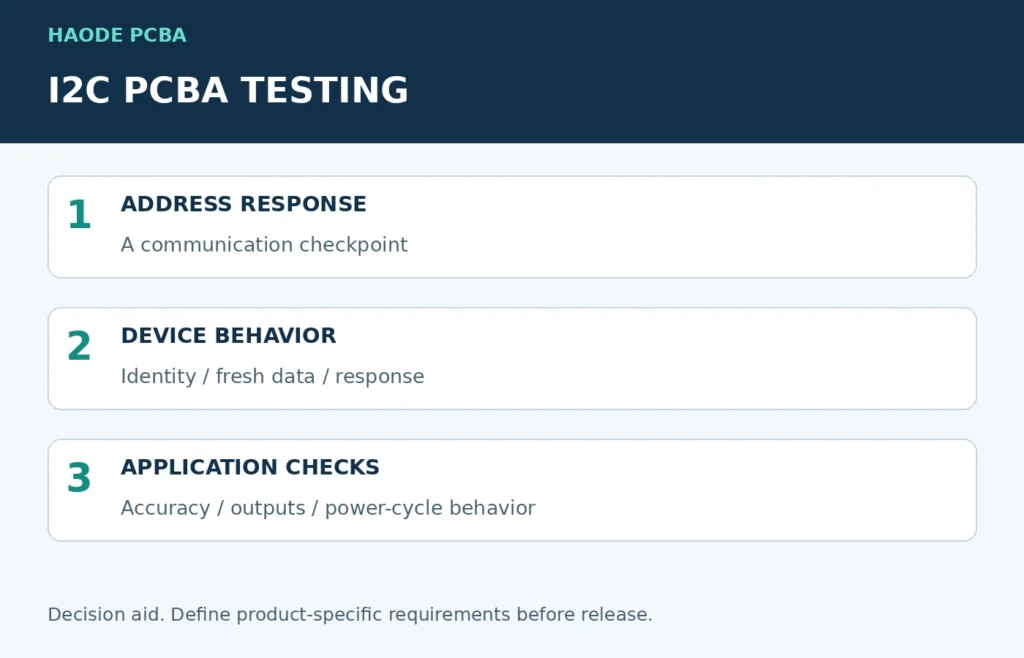
Illustrative coverage levels. Select actual tests and limits for the product.
What Does An I2C Address Scan Actually Prove?
A typical scanner attempts transactions at candidate addresses and reports acknowledgment. The precise operation depends on the scanner implementation, so the test procedure should identify its code and configuration.
Texas Instruments’ explanation of the I2C bus describes ACK and NACK as part of byte transfer. An acknowledgment is communication evidence; it is not a certificate that the attached sensor meets its application specification.
For production, use a targeted transaction appropriate to each expected device rather than assuming a general-purpose scanner is harmless or equally meaningful on every bus.
An address response can be useful for locating a missing device or communication fault. However, it may not identify which device responded, and it does not necessarily reveal multiple devices configured to the same address.
The scope belongs in the PCBA functional-test specification, alongside the firmware revision and the expected address map.
Which Faults Could Still Pass A Scan?
Consider a board containing a temperature sensor, configuration memory, an MCU, and a display. The following are coverage gaps to evaluate, not claims that every listed fault occurs on every design.
| Passing Observation | Remaining Question | Additional Evidence |
|---|---|---|
| Sensor acknowledges | Is it the approved device or family? | Supported identification register or another approved identity check |
| Sensor register can be read | Is the result fresh and responsive to the input? | Conversion status and a controlled stimulus |
| Measurement looks plausible | Is it within the product’s required accuracy? | Defined reference, uncertainty, and acceptance limits |
| Memory acknowledges | Can the required data be written and retained? | Controlled write/read and persistence test where applicable |
| MCU displays “PASS” | Are display segments, colors, or pixels actually operating? | Approved pattern with visual or automated inspection |
| Bus works once | Does it work at the released speed and required operating conditions? | Defined repeated transactions and error logging |
| Device reads correctly | Does an independent alert or interrupt path work? | Trigger and observe that path if the product uses it |
Do not treat this matrix as a demand to test every possible feature. Select the rows that correspond to customer requirements and credible manufacturing failures.
When access is missing, address it in design for testability before committing to the fixture. Some meaningful tests require access to signals that a simple programming connector does not expose.
How Do You Turn A Sensor Datasheet Into A Production Test?
Start with the exact sensor and application. Identify the registers or pins needed to configure it, obtain a fresh result, and observe any required output.
For example, the TI TMP117 datasheet documents a device-identification register, measurement behavior, configuration, and alert functions. These provide distinct things an engineer can check. They do not create a ready-made acceptance procedure for every temperature-sensing product.
An identity check establishes only the identity information that the device exposes. It should not be represented as proof of supply-chain authenticity.
Communication Test
Record the expected device, address, transaction, and allowed response. Handle timeouts and invalid results explicitly. Otherwise, the software may accidentally retain an old value after a failed read.
Response Test
Apply a controlled input and confirm the required change within a defined time. For a temperature sensor, fixture heat flow and settling matter. A sensor still equilibrating with its surroundings can produce a misleading comparison.
For other sensor types, define the appropriate stimulus: pressure, light, motion, or an electrical input. The production team needs the method and reference conditions, not simply “check sensor.”
Accuracy Test
If the contract requires accuracy verification, specify the reference instrument, test points, stabilization criterion, and measurement uncertainty. Set limits from the product requirement and the validated measurement method.
Do not copy the component’s headline accuracy into the factory’s pass window without accounting for the assembled product and test setup. Likewise, a room-temperature comparison should not be presented as validation across the full operating range.
What Should A Useful Test Record Contain?
Replace a single overall result with enough detail to locate a failure and identify what passed. The following is an editable specification structure, not measured Haode production data.
| Field | What The Product Owner Must Define |
|---|---|
| Board identity | Serial number or agreed batch identity and hardware revision |
| Software identity | Test program, application image, and configuration revisions |
| Device checks | Expected targets, identification rules, and communication settings |
| Measurement checks | Stimulus, units, settling rule, limits, and reference equipment |
| Test outcome | Individual results, measured values, and overall disposition |
| Retest history | First failure, reason for retest, repair if any, and final approval |
Connect those records to PCBA traceability. A screenshot of “PASS” without board or software identity is difficult to use when investigating a later return.
How Can You Tell A Bad Board From A Bad Fixture?
A failed test is a signal to investigate, not immediate proof of a defective sensor. Contact, supply, cabling, fixture alignment, and test software can also affect the result.
Preserve the original log first. Then use an approved comparison, such as a controlled reference board or an alternate verified fixture position. Record what changed so the comparison remains meaningful.
However, a reference board is not an accuracy standard unless it has been characterized and maintained for that role. Use appropriate reference equipment for measurement acceptance.
Escalate unexplained failures through PCBA failure analysis. Repeatedly running the test until a green result appears conceals intermittent faults and weakens the evidence.
Which Tests Belong On Every Board?
Separate routine production screening from qualification and diagnostic testing. Run the agreed per-unit checks on every applicable assembly; use risk-based sampling or engineering testing for other requirements when the specification permits it.
| Test Purpose | Typical Use | Scope Decision |
|---|---|---|
| Routine screening | Identity, communication, selected functions | Define required checks and records for each shipped board |
| Process confirmation | First units after setup or an approved change | Verify the setup before continuing production |
| Qualification | Operating limits, environmental behavior, durability | Establish a separate plan with appropriate conditions and samples |
| Diagnosis | Unexpected failures or returns | Select tests from the evidence rather than repeating the entire plan blindly |
Use first article inspection to confirm the released setup. Keep any environmental testing requirements explicit rather than implying that a brief functional check proves long-term reliability.
Before committing to a volume order, request a PCBA quotation that separates fixture development, test-software work, per-unit test time, and any external equipment requirements.
What Should You Ask Haode Before Releasing A Sensor Board?
Provide the schematic, approved BOM, firmware, used sensor functions, operating requirements, and proposed acceptance limits. Ask which checks the proposed production process will perform and what records you will receive.
Agree who develops the fixture and software, who approves the limits, and how failures are handled. Where a test is outside the agreed scope, record that gap rather than leaving the buyer to infer coverage.
The objective of I2C PCBA testing is a clear statement of verified behavior. An address scan can contribute to that statement, but it cannot carry the entire shipment decision.